


Chapter 8. Dedicated Maps Terminal Menu
61200266L1-1 ATLAS 810
PLUS
User Manual 8-7
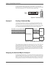
by-step procedures for creating a sample dedicated map based on the con-
nections and ports given in Table 8-1.
Configuring the Ports for Example 2
Begin by navigating to
Terminal Menu/Modules
. From this menu, configure
the various ports to match the framing parameters of the T1 line provided
by the telco.
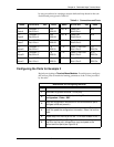
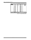
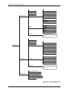
Table 8-1. Connections and Ports
Name
ATLAS 810
PLUS
Port
DS0s Name
ATLAS 810
PLUS
Port
DS0s
T1:
Data A
Controller T1
Slot 0 Port 1
9-24
RBS Off
V.35 - A Quad V.35
Slot 2/Port 1
N/A
T1:
Data B
Controller T1
Slot 0/Port 2
9-24
RBS Off
V.35 - B Quad V.35
Slot 2/Port 2
N/A
T1:
Data C
Quad T1/PRI
Slot 1/Port 1
9-24
RBS Off
V.35 - C Quad V.35
Slot 2/Port 3
N/A
T1:
Voice A
Controller T1
Slot 0/Port 1
1-8
RBS On
T1-D Quad T1/PRI DSX
Slot 1/Port 2
1-8
RBS On
T1:
Voice B
Controller T1
Slot 0/Port 2
1-8
RBS On
T1-D Quad T1/PRI DSX
Slot 1/Port 2
9-16
RBS On
T1:
Voice C
Quad T1/PRI
Slot 1/Port 1
1-8
RBS On
T1-D Quad/PRI DSX
Slot 1/Port 2
17-24
RBS On
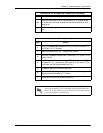
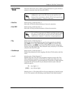
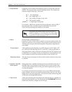
Instructions for Configuring the Ports
Step Action
1
Select
Slt / 0
(system controller T1/PRI port).
2
Set the line framing parameters by selecting
Menu /
Configuration / Frame
/ ESF
.
3
Copy this configuration information for use with additional ports.
(Navigate to
Prt
and press
C
.)
4
Navigate to the port index number of the second port (
Prt
) and
press
P
to paste the configuration information. Press
Y
to confirm
paste.
5
Repeat Step 4 for the first port of the T1/PRI card located in Slot 1.
6
Navigate to the V.35 port
Configuration
submenu and repeat
Step 2 for the first port, followed by a copy-and-paste to the
second and third ports (see Figure 8-4).