


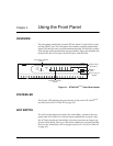
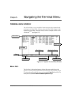


Chapter 4. Using the Front Panel
61200266L1-1 ATLAS 810
PLUS
User Manual 4-3
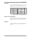
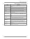
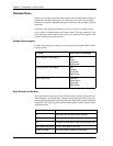
Table 4-2. ATLAS 810
PLUS
Front Panel Description
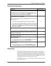
Feature Description
Controller Status LEDs
Indicates the status of both network interfaces. (See also Table 4-3 on
page 4-4.)
OK Indicates that both integral network interfaces are operating correctly.
Test Indicates that one of the network interfaces is in a test mode.
Error Blinks to indicate the occurrence of error events.
Alarm Indicates an alarm condition on one of the network interfaces.
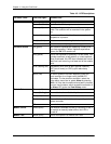
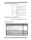
Module Slot Numbers
Illuminates to indicate that option modules are installed in the
corresponding slots.
Module Status LEDs
Displays, by row, the operational condition (
Status
,
Online
,
and
Test
) of
each module installed in the option slots.
(See also Table 4-3 on page 4-
4.)
Status Displays the operational condition of modules installed in the option
slots.
Online Indicates whether the module is available for use or is currently in use. If
the module is manually taken offline, this LED is turned off.
Test Indicates that one or more ports within a module are in test.
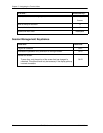
System LED
Indicates the general status of the entire ATLAS 810
PLUS
. A green light
indicates that conditions are normal. A red light indicates a system
problem or alarm condition. (See also Table 4-3 on page 4-4.)
ACO Switch
Clears the Alarm Relay connection located on the rear panel of the
ATLAS 810
PLUS
.
CRAFT Port
Allows the ATLAS 810
PLUS
to connect to a computer or modem using
the CRAFT port (an EIA-232 port).