


Chapter 9. Dial Plan Terminal Menu
61200266L1-1 ATLAS 810
PLUS
User Manual 9-3
>
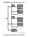
NETWORK
TERM
This menu allows the user to define option parameters for ports which ter-
minate a connection from the Network (PSTN).
» Slot/Svc
Write security: 3; Read security: 5
Selects the ATLAS slot that terminates a Network connection.
» Port/PEP
Write security: 3; Read security: 5
Selects the ATLAS port that terminates a Network connection.
» Sig
Write security: 3; Read security: 5
Defines the type of signaling being used for this connection (endpoint).
Select
RBS
for a T1 using Robbed Bit Signaling,
PRI
for a Primary Rate
ISDN interface, and
NFAS
for a Primary Rate ISDN interface using Non-
Facility Associated Signaling. This selection is only necessary if a T1/PRI is
selected as the Slot/Port type.
» Out#Accept
Write security: 3; Read security: 5
Defines the parameters for the outgoing calls that ATLAS sends to the Net-
work.
»» Src ID
Write Security: 3 Read Security: 5
Identifies the call source ID from which this endpoint accepts calls. This
field simplifies the creation of a Dial Plan in applications where the crite-
rion for switching calls to a certain endpoint is a function of which endpoint
originated the call. Source ID may be entered with the usual wild card
entries (except $).
Default value = 0. The default ID for all source endpoints is 0 and all accept
#'s is 0. This results in all calls being routed based on the dialed number.
In applications where two ATLAS units are used in a point-to-point
configuration, a port in the ATLAS at one end would act as the
Network (User termination), while the ATLAS at the opposite end
would be terminating a “Network” connection.
There may be more than one “endpoint” associated with a particular
port. If a T1 is connected to the PSTN, some DS0s may be used for
long distance, while others are used for local calls. These would
constitute two “endpoints” (trunks) over a single physical port.
X
=
any digit 0—9
[1,3,5]
=
any of these digits