


Chapter 2. Installation
61200266L1-1 ATLAS 810
PLUS
User Manual 2-7
Alarm Relay Connection
This connection alerts the user when a selected alarm condition exists. The
four-pin, removable terminal block connects with external wiring. To make
the appropriate connections, remove the block, connect wiring as needed,
and return the terminal block to the connector socket. Clear the alarm con-
dition by pressing the Alarm Cut-Off (ACO) switch located on the font panel
of the ATLAS 810
PLUS
.
Connection
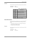
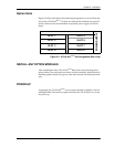
Table 2-4 shows the pinout for the Alarm Relay connector.
Mon
The MON (monitor) test jack provides a bridged access jack for non-intru-
sive monitoring of the T1 circuits receiving data. When connected to this
jack, the test equipment should be configured for a bridged termination.
After the appropriate connections have been made, tighten the
screws using a flathead screwdriver before reinserting the terminal
block into the rear panel of the ATLAS 810
PLUS
.
Table 2-4. Alarm Relay Connector Pinout
Pin Name Description
1 Normally Closed (NC) Opens when a selected alarm condition
is present.
2 Normally Open (NO) Closes when a selected alarm condition
is present.
3 Common (COM) Common connection between external
circuitry and NC or NO terminal.
4
Chassis Ground (GND)