


104 AT-WR4500 Series - IEEE 802.11abgh Outdoor Wireless Routers
RouterOS v3 Configuration and User Guide
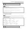
Example
The following text can be observed just after adding an OSPF network:
admin@AT-WR4562] routing ospf> neighbor print
router-id=10.0.0.204 address=10.0.0.204 priority=1 state="2-Way"
state-changes=0 ls-retransmits=0 ls-requests=0 db-summaries=0
dr-id=0.0.0.0 backup-dr-id=0.0.0.0
[admin@AT-WR4562] routing ospf>
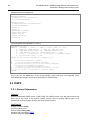
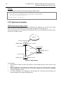
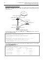
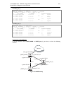
5.3.8 Application Examples
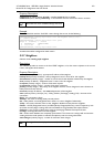
OSPF backup without using a tunnel
Let us assume that the link between the routers OSPF-Main and OSPF-peer-1 is the main one. If it goes
down, we want the traffic switch over to the link going through the router OSPF-peer-2.
This example shows how to use OSPF for backup purposes, if you are controlling all the involved routers,
and you can run OSPF on them.
main_gw 192.168.0.11
[OSPF_peer_2]
Cost=1
Cost=1
Cost=1
to_peer1 10.3.0.2
to_main 10.2.0.1
backup 10.3.0.1
to_peer2 10.2.0.2
to_peer1 10.1.0.2
[OSPF_MAIN]
to_main 10.1.0.1
[OSPF_peer_1]
Internet
Figure 13: OSPF Backup
In this example:
1. We introduce an OSPF area with area ID=0.0.0.1, which includes all three routers shown on the
diagram
2. Only the OSPF-Main router will have the default route configured. Its interfaces peer1 and peer2
will be configured for the OSPF protocol. The interface main_gw will not be used for distributing
the OSPF routing information
3. The routers OSPF-peer-1 and OSPF-peer-2 will distribute their connected route information, and
receive the default route using the OSPF protocol