


AT-WR4500 Series - IEEE 802.11abgh Outdoor Wireless Routers 77
RouterOS v3 Configuration and User Guide
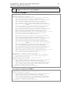
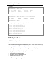
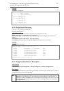
On Router 1:
[admin@AT-WR4562] ip address> add address=10.10.10.1/24 interface=test
[admin@AT-WR4562] ip address> print
Flags: X - disabled, I - invalid, D - dynamic
# ADDRESS NETWORK BROADCAST INTERFACE
0 10.0.0.204/24 10.0.0.0 10.0.0.255 ether1
1 10.20.0.1/24 10.20.0.0 10.20.0.255 pc1
2 10.10.10.1/24 10.10.10.0 10.10.10.255 test
[admin@AT-WR4562] ip address>
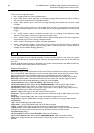
On Router 2:
[admin@AT-WR4562] ip address> add address=10.10.10.2/24 interface=test
[admin@AT-WR4562] ip address> print
Flags: X - disabled, I - invalid, D - dynamic
# ADDRESS NETWORK BROADCAST INTERFACE
0 10.0.0.201/24 10.0.0.0 10.0.0.255 ether1
1 10.10.10.2/24 10.10.10.0 10.10.10.255 test
[admin@AT-WR4562] ip address>
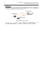
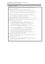
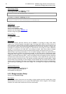
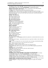
If it set up correctly, then it is possible to ping Router 2 from Router 1 and vice versa:
[admin@AT-WR4562] ip address> /ping 10.10.10.1
10.10.10.1 64 byte pong: ttl=255 time=3 ms
10.10.10.1 64 byte pong: ttl=255 time=4 ms
10.10.10.1 64 byte pong: ttl=255 time=10 ms
10.10.10.1 64 byte pong: ttl=255 time=5 ms
4 packets transmitted, 4 packets received, 0% packet loss
round-trip min/avg/max = 3/10.5/10 ms
[admin@AT-WR4562] ip address> /ping 10.10.10.2
10.10.10.2 64 byte pong: ttl=255 time=10 ms
10.10.10.2 64 byte pong: ttl=255 time=11 ms
10.10.10.2 64 byte pong: ttl=255 time=10 ms
10.10.10.2 64 byte pong: ttl=255 time=13 ms
4 packets transmitted, 4 packets received, 0% packet loss
round-trip min/avg/max = 10/11/13 ms
[admin@AT-WR4562] ip address>
4.5 Bridge Interfaces
D o c u m e n t r e v i s i o n :
2 . 3 ( F r i A u g 1 8 1 1 : 5 6 : 4 5 G M T 2 0 0 6
A p p l i e s t o :
V 2 . 9
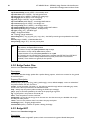
4.5.1 General Information
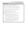
Summary
MAC level bridging of Ethernet, Ethernet over IP (EoIP) and Atheros wireless interfaces are supported.
All 802.11a, 802.11b, and 802.11g client wireless interfaces (ad-hoc, infrastructure or station mode)
do not support this because of the limitations of 802.11. However, it is possible to bridge over a wireless
link using the WDS feature or Ethernet over IP protocol.
For preventing loops in a network, you can use the Spanning Tree Protocol (STP). This protocol is also
used for configurations with backup links.
Main features:
• Spanning Tree Protocol (STP) and Rapid Spanning Tree Protocol (RSTP)
• Multiple bridge interfaces
• Bridge associations on a per-interface basis
• MAC address table can be monitored in real time
• IP address assignment for router access
• Bridge interfaces can be filtered and NATed
• Support for brouting based on bridge packet filter