


154 AT-WR4500 Series - IEEE 802.11abgh Outdoor Wireless Routers
RouterOS v3 Configuration and User Guide
8.2 Interface Bonding
Document revisi on: 1.1 (oct-26-2004)
Applies to: V2.9
8.3 General Information
8.3.1 Summary
Bonding is a technology that allows to aggregate multiple ethernet-like interfaces into a single virtual link,
thus getting higher data rates and providing failover.
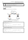
8.3.2 Quick Setup Guide
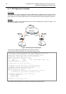
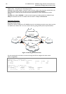
Let us assume that we have 2 NICs in each router (Router1 and Router2) and want to get maximum
data rate between 2 routers. To make this possible, follow these steps:
Make sure that you do not have IP addresses on interfaces which will be enslaved for bonding interface!
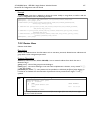
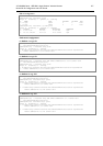
Add bonding interface on Router1:
[admin@Router1] interface bonding> add slaves=ether1,ether2
And on Router2:
[admin@Router2] interface bonding> add slaves=ether1,ether2
Add addresses to bonding interfaces:
[admin@Router1] ip address> add address=172.16.0.1/24 interface=bonding1
[admin@Router2] ip address> add address=172.16.0.2/24 interface=bonding1
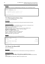
Test the link from Router1:
[admin@Router1] interface bonding> /pi 172.16.0.2
172.16.0.2 ping timeout
172.16.0.2 ping timeout
172.16.0.2 ping timeout
172.16.0.2 64 byte ping: ttl=64 time=2 ms
172.16.0.2 64 byte ping: ttl=64 time=2 ms
A bonding interface needs a couple of seconds to get connectivity with its peer.
Specifications
Packages required: system
License required: Level1
Submenu level: /interface bonding
Standards and Technologies: None
Hardware usage: Not significant
8.3.3 Related Documents
Linux Ethernet Bonding Driver mini-howto