


114 AT-WR4500 Series - IEEE 802.11abgh Outdoor Wireless Routers
RouterOS v3 Configuration and User Guide
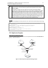
ISP1 gives us 2Mbps and ISP2 - 4Mbps so we want a traffic ratio 1:2 (1/3 of the source/destination IP
pairs from 192.168.0.0/24 goes through ISP1, and 2/3 through ISP2).
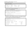
IP addresses of the router:
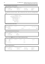
[admin@ECMP-Router] ip address> print
Flags: X - disabled, I - invalid, D - dynamic
# ADDRESS NETWORK BROADCAST INTERFACE
0 192.168.0.254/24 192.168.0.0 192.168.0.255 Local
1 10.1.0.2/28 10.1.0.0 10.1.0.15 Public1
2 10.1.1.2/28 10.1.1.0 10.1.1.15 Public2
[admin@ECMP-Router] ip address>
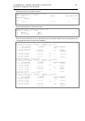
Add the default routes - one for ISP1 and 2 for ISP2 so we can get the ratio 1:3:
[admin@ECMP-Router] ip route> add gateway=10.1.0.1,10.1.1.1,10.1.1.1
[admin@ECMP-Router] ip route> print
Flags: X - disabled, A - active, D - dynamic,
C - connect, S - static, r - rip, b - bgp, o - ospf
# DST-ADDRESS G GATEWAY DISTANCE INTERFACE
0 ADC 10.1.0.0/28 Public1
1 ADC 10.1.1.0/28 Public2
2 ADC 192.168.0.0/24 Local
3 A S 0.0.0.0/0 r 10.1.0.1 Public1
r 10.1.1.1 Public2
r 10.1.1.1 Public2
[admin@ECMP-Router] ip route>
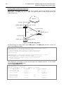
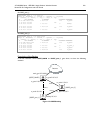
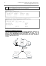
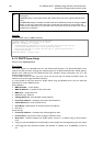
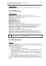
Standard Policy-Based Routing with Failover
This example will show how to route packets, using an administrator defined policy. The policy for this
setup is the following: route packets from the network 192.168.0.0/24, using gateway 10.0.0.1, and
packets from network 192.168.1.0/24, using gateway 10.0.0.2. If GW_1 does not respond to pings, use
GW_Backup for network 192.168.0.0/24, if GW_2 does not respond to pings, use GW_Backup also for
network 192.168.1.0/24 instead of GW_2.
The setup:
Network
10.0.0.0/24
192.168.0.0/24
Interface: Public
IP: 10.0.0.7/24
Interface: Local1
IP: 192.168.0.1/24
192.168.1.0/24
Interface: Local2
IP: 192.168.1.1/24
[GW_1]
IP: 10.0.0.2
[GW_2]
IP: 10.0.0.3
[GW_Backup]
IP: 10.0.0.1
Figure 17: Standard Policy-Based Routing with Failover