


DCP Cabling and Administration 9-15
_ ______________________________________________________________________________________
_ ______________________________________________________________________________________
_ ______________________________________________________________________________________
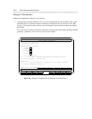
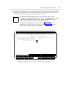
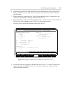
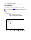
6. Assign line appearances to the DCP equipment location. Make the entries as shown in Figure 9-9,
Manager II Administration for DCP Ports (Proc 052, Word 1). The extension shown in Field 8 is
only an example.
7. The first extension is assigned to Device Type 0 (Field 6) Member 0 (Field 7). Repeat step 6, only
use Device Type 0 Member 1 and assign a different extension to it.
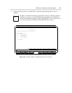
8. Repeat steps 6 and 7 for the second DCP equipment location. Assign two other extension numbers to
Device Type 0 (Field 6) Members 0 and 1 (Field 7) for this equipment location.
If desired, you may display the extensions using Proc 052, Word 2.
ENHANCED MODE - PROCEDURE: 052, WORD: 1
MULTIAPPEARANCE TERMINAL/DATA MODULE - LINE APPEARANCE
TERMINAL EQUIPMENT LOCATION DEVICE ID
1. Module: 0 6. Device Type: 0 Basic Set
2. Cabinet: 1 7. Member (button): 0
3. Carrier: 1 EXTENSION APPEARANCE ID
4. Slot: 18 8. Extension: 32330
5. Circuit: 3 9. Line Appearance: 1
10. Line Type: 1 Prime line
11. Ringing Type: 1 Ringing
12. Home Terminal: 1 Yes
13. Originating Only: 0 No
14. SAC Group: 0 No
DISPLAY ONLY
15. Button Type: 1 Line appearance (052w1)
Connected to CC0 ON-LINE ♥ MAJOR
MINOR RUN TAPE BUSY OUT IN USE WAIT
enter command: _
3 Data 5 Help 6 Field 7 Input 8 Cmds
Figure 9-9. Manager II Administration for DCP Ports (Proc 052, Word 1)
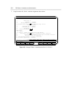
9. After the extensions are assigned here, their BCCOS may be reset to 1. Go back to Procedure 000,
Word 3 and check if the BCCOS is still 6. If not, reset it to 6 if necessary. Check each of the
AUDIX networking extensions.