Contents xi
_ ______________________________________________________________________________________
_ ______________________________________________________________________________________
_ ______________________________________________________________________________________
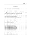
LIST OF FIGURES
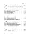
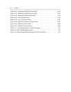
Figure 1-1. H600-330, Group 1 AUDIX Special Null-Modem Cable . . . . . . . 1-8
Figure 1-2. H600-331, Group 2 AUDIX Networking Breakout Cable . . . . . . . 1-9
Figure 1-3. H600-331, Group 1 AUDIX Networking Breakout Cable . . . . . . . 1-10
Figure 2-1. Dedicated RS-232 Network of Two AUDIX Systems . . . . . . . . 2-2
Figure 2-2. Dedicated RS-232 Network of Two AUDIX Systems and a PC (Low Traffic
Only) . . . . . . . . . . . . . . . . . . . . . . . . . . 2-3
Figure 2-3. Dedicated RS-232 Network of Three AUDIX Systems (Low Traffic
Only) . . . . . . . . . . . . . . . . . . . . . . . . . . 2-3
Figure 2-4. Dedicated RS-232 Network of Three AUDIX Systems and a
PC . . . . . . . . . . . . . . . . . . . . . . . . . . 2-4
Figure 2-5. Dedicated RS-232 Extended Connections . . . . . . . . . . . 2-6
Figure 3-1. Dedicated and Switched RS-232 Network for a Single Switch . . . . . 3-3
Figure 3-2. Switched RS-232 Network for a Single Switch . . . . . . . . . . 3-4
Figure 3-3. Switched RS-232 Network for Separate Locations . . . . . . . . . 3-5
Figure 3-4. Switched RS-232 Network for Separate Locations and a PC . . . . . 3-6
Figure 3-5. Converting RS-232 Channels to DCP . . . . . . . . . . . . . 3-7
Figure 4-1. DCP Mode 1 Network Using Switched 56 Service . . . . . . . . . 4-3
Figure 4-2. PC Added to a DCP Network . . . . . . . . . . . . . . . . 4-5
Figure 5-1. Typical Rack-Mounted Modem Pool Using D-Lead Control . . . . . . 5-2
Figure 5-2. Typical Stand-Alone Modem Pool (No D-Lead Control) . . . . . . . 5-3
Figure 5-3. DCP Mode 2 Network (Modem Pooling) . . . . . . . . . . . . 5-4
Figure 6-1. DCP Mode 3 Network for a Single Switch . . . . . . . . . . . 6-3
Figure 6-2. DCP Mode 3 Network for a Non-DCP Switch . . . . . . . . . . 6-4
Figure 6-3. DCP Mode 3 Network for Multiple Locations . . . . . . . . . . . 6-6
Figure 6-4. DCP Mode 3 Network for a 5ESS Switch . . . . . . . . . . . . 6-7
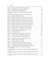
Figure 7-1. RS-232 and DCP at the Same AUDIX . . . . . . . . . . . . . 7-2
Figure 7-2. High-Speed Switched RS-232 and DCP AUDIX Connections . . . . . 7-3
Figure 7-3. Using DCP for AUDIX Systems and RS-232 for a PC . . . . . . . . 7-4
Figure 7-4. RS-232 and DCP at Separate Locations . . . . . . . . . . . . 7-5
Figure 8-1. Dedicated RS-232 Connection (within 10 feet) . . . . . . . . . . 8-2
Figure 8-2. Dedicated RS-232 Connection (within 50 feet) . . . . . . . . . . 8-3


