


DCP Mode 2 Installation and Administration 11-13
_ ______________________________________________________________________________________
_ ______________________________________________________________________________________
_ ______________________________________________________________________________________
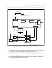
LINE
LINE
SN243
7400A
7400A
H600-331
GROUP 1
CROSS-
CONNECT
DCP
25-PAIR
D-LEAD
DATA MODE
CONTROL
CO
DID
TIE
T/R
T/R
BRIDGING
ADAPTER
MODEM
MODEM
M25B (RS-232)
M25B (RS-232)
D8W-87
(8 CORDS)
105A MOUNTING
77A MOUNTING
ADAPTER HARNESS
25-PAIR
SN255C
SN261B
P1
SYSTEM 85 *
*System 75 boards differ from those shown
J2 J1
SN270B
SN270B
ACC(E)
AUDIX
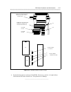
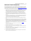
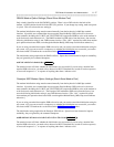
Figure 11-6. AUDIX Networking (Modem Pooling) with 7400A DSUs
18. From the back of the rack, connect the appropriate M25B cable to its RS-232 port on the back of each
data module. Tighten the connector screws to hold the cables securely in place.
19. Drape each interface cable through its plastic twist lock and twist the top ends of the lock to secure
each cable. Make sure each modem is interconnected through the RS-232 cable to the 7400A in the
corresponding rack position.
20. To test the remote connection and the administration of the system, run the self-test as described in
Section 2 of the 7400A Data Module User’s manual.