


11-12 DCP Mode 2 Installation and Administration
________________________________________________________________________________________________
________________________________________________________________________________________________
________________________________________________________________________________________________
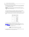
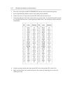
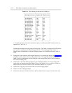
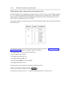
Table 11-1. 7400A Settings for Modem Pool (9600 bps)
_ ___________________________________________
Set Option Screens Option and Value Screens
_ ___________________________________________
_ ___________________________________________
Set 300 Speed? 300 Off
Set 1200 Speed? 2400 Off
Set 2400 Speed? 2400 Off
Set 4800 Speed? 4800 Off*
Set 9600 Speed? 9600 On
Set 19200 Speed? 19200 Off
Set AT Control? AT Off
Set CI Lead? CI On
Set CI2 Lead? CI2 On
Set CH Lead CH On
Set CH2 Lead? CH2 On
Set LL Lead? LL On
Set Remote Loop? Remloop Grant
Set RL Lead? RL On
Set Sigls Disc? Sigls Disc On
Set TM Lead? TM On
_ ___________________________________________
* To enable stepdown (slower data transmission speed), set 4800 speed to ON. On the modem, set
Options 50, 56, and 73 to y.
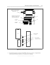
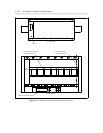
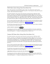
Continue the installation according to the following steps. The 7400A is configured for DTE modem
pool operation with D-lead controlled 2296-type modems. The mounting package includes an
adapter harness (WP90780L0), an OR-6316 bridging adapter, and a 2296 modem control cable (D-
Lead).
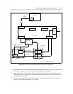
13. Connect the 50-pin connector on the adapter harness to P1 on the bridging adapter [see Figure 11-6,
AUDIX Networking (Modem Pooling) With 7400A DSUs]. Then plug each numbered connector
(D8W-87 cords) on the harness into the LINE jack on the corresponding 7400A (see the numbered
slots on the mounting rack).
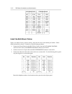
14. Connect the 25-pair cable from the switch to J1 on the bridging adapter. For correct wiring of the
switch cable, see the table titled WP90780L0 25-Pair Cable Adapter for Use with Direct Cabling to
Multiple Mount for DCP Installations in the 7400A Data Module User’s manual.
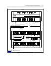
15. Connect the 50-pin plug of the D-Lead cable to J2 on the bridging adapter.
16. Put the cover on the bridging adapter.
17. Connect the other end of the D-Lead cable to the Data Mode Control connector on the modem rack.