9. DCP Cabling and Administration
_ ______________________________________________________________________________________
_ ______________________________________________________________________________________
_ ______________________________________________________________________________________
This chapter provides explanations and illustrations for the cabling, translation, and use of the AUDIX
networking channels for supported host switches. If you are setting up a connection requiring interlocation
facilities, use this chapter to set up the Digital Communications Protocol (DCP) channels from the AUDIX
system to the switch, then go to Chapter 10, DCP Mode 1 Installation and Administration, Chapter 11,
DCP Mode 2 Installation and Administration, or Chapter 12, DCP Mode 3 Installation and Administration
to set up the interlocation facilities.
ACC(E) WIRING TO THE SWITCH
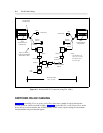
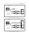
For a System 75, System 85, DEFINITY Generic 1, Generic 2, or Generic 3, the DCP circuits at the switch
are normally wired to the cross-connect field using 25-pair cable. If you are connecting the AUDIX system
to a MERLIN II, D8W-87 modular cord is always used (that is, the cross-connect field is not required).
NOTE
MERLIN II is supported for local networking only. Remote networking/modem pooling
with MERLIN II is not supported.
System 75, System 85, and DEFINITY Communications Systems
For the System 75, System 85, and DEFINITY Generic 1, Generic 2, or Generic 3, the AUDIX DCP ports
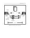
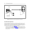
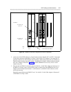
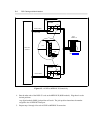
must be wired to the switch through the cross-connect field. Figure 9-1, DCP Cabling to the Switch Using
the H600-331, Group 2 Cable, shows how this is done.
9-1


