


5-2 DCP Mode 2 Networks — Modem Pooling
________________________________________________________________________________________________
________________________________________________________________________________________________
________________________________________________________________________________________________
GENERAL INFORMATION
DCP Mode 2 networking uses the DCP interface between the AUDIX system and the switch. Analog or
voice-grade data facilities are used between customer locations. When the switch is a System 85 or
DEFINITY Generic 2, the AUDIX system can use up to six ports at any given time. When the switch is a
System 75, Generic 1, or Generic 3, up to four ports may be used at any given time.
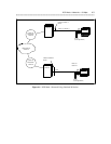
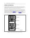
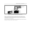
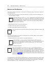
Figure 5-1, Typical Rack-Mounted Modem Pool Using D-Lead Control, shows a modem pool where a D-
Lead is used between the modems and data modules. This arrangement is usually shared by two or more
switch applications. The customer can use this arrangement for AUDIX systems so long as the equipment
and their option settings are compatible. (Compatible equipment is provided later in this chapter.
Compatible option settings are provided in Chapter 11, DCP Mode 2 Installation and Administration.) The
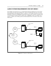
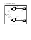
customer could also use what is called stand-alone modem pooling. See Figure 5-2, Typical Stand-Alone
Modem Pool (No D-Lead Control).
Use 46A2 mounting
if MTDMs are used
instead of 7400As.
NOTE:
105A MOUNTING
WITH 8 MODEMS
105A MOUNTING
WITH 8 MODEMS
2
2
9
6
A
2
2
9
6
A
2
2
9
6
A
2
2
9
6
A
2
2
9
6
A
2
2
9
6
A
2
2
9
6
A
2
2
9
6
A
2
2
9
6
A
2
2
9
6
A
2
2
9
6
A
2
2
9
6
A
2
2
9
6
A
2
2
9
6
A
2
2
9
6
A
2
2
9
6
A
77A MOUNTING
WITH 8 DATA SETS
7
4
0
0
A
7
4
0
0
A
7
4
0
0
A
7
4
0
0
A
7
4
0
0
A
7
4
0
0
A
7
4
0
0
A
7
4
0
0
A
7
4
0
0
A
7
4
0
0
A
7
4
0
0
A
7
4
0
0
A
7
4
0
0
A
7
4
0
0
A
7
4
0
0
A
77A MOUNTING
WITH 8 DATA SETS
7
4
0
0
A
Figure 5-1. Typical Rack-Mounted Modem Pool Using D-Lead Control