


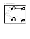

DCP Mode 2 Networks — Modem Pooling 5-7
_ ______________________________________________________________________________________
_ ______________________________________________________________________________________
_ ______________________________________________________________________________________
DCP Interface for the Digital Side of the Modem Pool
The following digital lines are required to terminate the digital side of a modem pool:
• System 75, Generic 1, or Generic 3:
One TN754 or TN754B Digital Line port is required for each modem pool pair. The ports used for the
modem pool must appear on a circuit pack(s) separate from the pack(s) used for the AUDIX channels.
• Generic 2 (universal module):
One TN754 or TN754B Digital Line port is required for each modem pool pair.
• System 85 and Generic 2 (traditional module):
One SN270B General Purpose Port is required for each modem pool pair.
Analog (Tip and Ring) Interface to the Interlocation Facilities
One of the following analog trunk circuits is required for terminating interlocation analog facilities at the
switch:
• System 75, Generic 1, Generic 2 (universal module), or Generic 3:
— TN747B Central Office (CO) Trunk (1200 to 9600 bps)
— TN753 Direct Inward Dialing (DID) Trunk (1200 to 9600 bps)
— TN760B Tie Trunk (1200 to 9600 bps)
• System 85 or Generic 2 (traditional module):
— SN230B CO Trunk (1200 to 9600 bps)
— SN232B DID Trunk (1200 to 9600 bps)
— SN233C Tie Trunk (1200 to 9600 bps)
Analog Interface for the Analog Side of the Modem Pool
The following analog lines are required to terminate the analog side of the modem pool:
• System 75, Generic 1, Generic 2 (universal module), or Generic 3:
One TN742 or TN746B Analog Line port is required for each modem pool pair.
• System 85 and Generic 2 (traditional module):
One SN243B Analog Data Port is required for each modem pool pair.