


Network Considerations A-7
_ ______________________________________________________________________________________
_ ______________________________________________________________________________________
_ ______________________________________________________________________________________
DIAL PLAN:
3000-3999
5000-5999
DIAL PLAN:
4000-4999
DIAL PLAN:
3000-5999
ADDRESS RANGES:
3000-4999
5000-5999
AUDIX
3
AUDIX
2
AUDIX
1
DCS
NODE 3
DCS
NODE 2
DCS
NODE 1
SWITCH
3
SWITCH
2
SWITCH
1
DIAL PLAN:
7000-7999
ADDRESS RANGES:
3000-4999
5000-5999
7000-7999
ADDRESS RANGES:
2000-2999
3000-4999
DIAL PLAN:
2000-4999
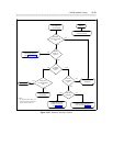
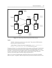
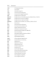
Figure A-3. Address Ranges When Dealing with a DCS Environment
Legend:
‘‘Dial Plan’’ indicates the extensions in use at the switch. These are both AUDIX subscriber
extensions and non-subscriber extensions.
‘‘Address Ranges’’ indicates the extensions assigned on the system : translation :
machine : audix/amis/call delivery form for the local system.
The purpose of Figure A-3 is to show that the address ranges assigned at AUDIX system 3 should include
the dial plan of the entire DCS environment (Nodes 1 through 3), even though AUDIX system 3 serves
only Node 1. The reason for this is that a caller at Switch 2, after unsuccessfully reaching a ‘‘live’’ person
at Switch 3, cannot transfer out of the AUDIX system to a person at Node 2 or Node 3 unless the
extensions at those nodes appear in the address range(s) along with Node 1’s.
Figure A-3 also shows how multiple ranges and duplicated ranges are used as opposed to using 0000 –
9999 at all systems. Using 0000 – 9999 would require memory allocation for extensions that do not exist.