


6-4 DCP Mode 3 Networks — 64 Kbps
________________________________________________________________________________________________
________________________________________________________________________________________________
________________________________________________________________________________________________
H600-331
GROUP 1
H600-331
GROUP 1
D8W-87
CORDS
D8W-87
CORDS
451A
ADAPTERS
451A
ADAPTERS
CONTROL LINK
VOICE PORTS
ALARM LINK
CONTROL LINK
VOICE PORTS
ALARM LINK
NON-DCP
SWITCH
II
MERLIN
.
.
.
.
.
.
.
.
.
.
.
.
.
.
.
.
.
.
.
.
.
.
.
.
.
.
.
. .
.
.
.
.
.
.
.
.
.
.
.
.
.
.
.
.
.
.
.
.
.
.
.
.
.
.
.
.
.
.
AUDIX
AUDIX
DCP DCP
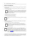
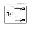
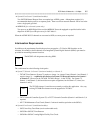
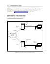
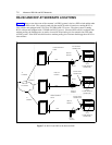
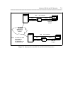
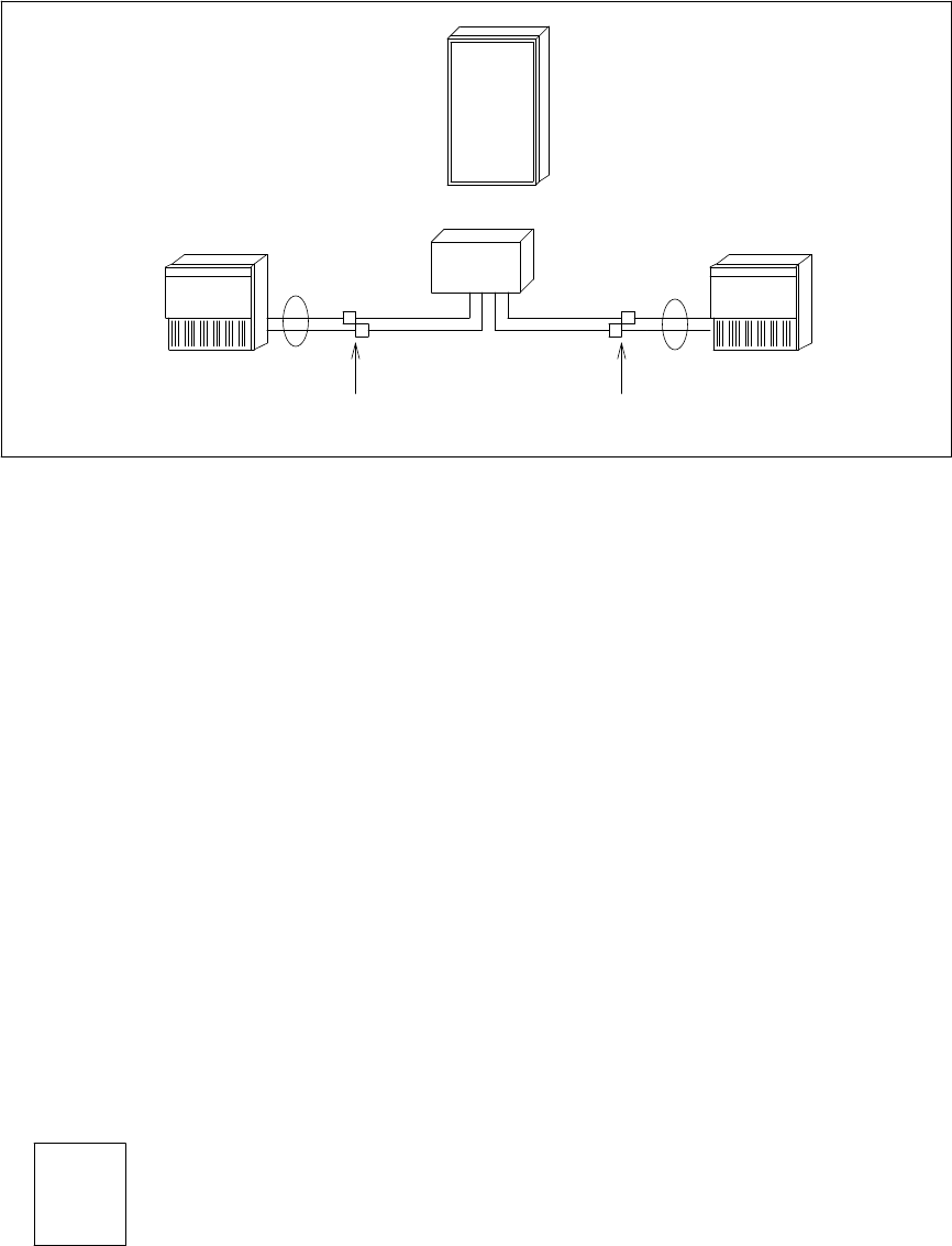
Figure 6-2. DCP Mode 3 Network for a Non-DCP Switch
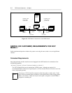
SWITCH (OR CUSTOMER) REQUIREMENTS FOR DCP
MODE 3
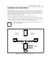
Switch requirements depend on whether the systems are serving the same switch or are serving different
switches.
Colocated Requirements
One of the following switches must be used and equipped with a DCP interface for termination of the
AUDIX DCP channels:
• System 75, Generic 1, Generic 2 (universal module), or Generic 3:
Two TN754 Digital Line ports are required per AUDIX system. Although not required, it is
recommended that the circuits be on separate packs so all four network channels will not be lost in the
event a single pack goes bad.
NOTE
All ports on a TN754 should be assigned as either lines (pdm) or trunks (tdm). Trunk
ports will have problems when assigned on circuit packs that have other ringing stations
(that is, line circuits). Make sure no ports on the pack is assigned as a trunk (TDM) or
assigned to a modem pool.