


11-6 DCP Mode 2 Installation and Administration
________________________________________________________________________________________________
________________________________________________________________________________________________
________________________________________________________________________________________________
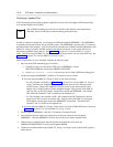
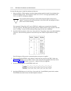
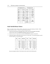
10 Position Switch 12 Position Switch
_ ________________________________________
_ ________________________________________
OFF < LOW FDX < HDX
_ ________________________________________
OFF < 300 ASYNC < SYNC
_ ________________________________________
OFF < 1200 INT < SLV
_ ________________________________________
OFF < 2400 OFF > DISC
_ ________________________________________
OFF < 4800 OFF > KYBD
_ ________________________________________
OFF > 9600 OFF < PRTY
_ ________________________________________
OFF < 19.2K 0/EV < 1/OD
_ ________________________________________
OFF < 56K SPARE <
_ ________________________________________
OFF < 64K SPARE <
_ ________________________________________
OFF < TRBK PL > SW
_ ________________________________________
OFF > SIGLS
_ ________________________________________
SPARE <
_ ________________________________________
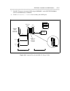
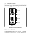
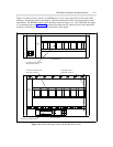
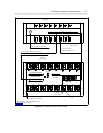
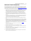
Install the Multi-Mount Cables
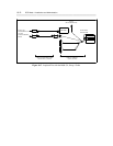
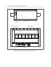
Figure 11-4, Modem Pooling Cabinet Cabling, shows the rear view of the modem-pool cabinet. Cables
should be installed as shown. For details, see the following procedures:
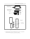
1. Connect the D Lead Control cable (RS-232C to 25-pair) from the DATA MODE CONTROL
connector on the 105A to the MODEM CONTROL connector on the 46A2.
2. Connect one end of a 25-pair cable to the RJ21X PERMISSIVE connector on the 105A.
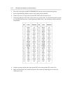
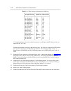
3. Connect the other end of this cable to the switch cross-connect field. Use the following table to patch
a tip and ring pair to a switch analog port.
_ ____________________________________________________
Pin Color Function Pin Color Function
_ ____________________________________________________
1 W/BL R (Line 1) 26 BL/W T (Line 1)
2 W/O R (Line 2) 27 O/W T (Line 2)
3 W/G R (Line 3) 28 G/W T (Line 3)
4 W/BR R (Line 4) 29 BR/W T (Line 4)
5 W/S R (Line 5) 30 S/W T (Line 5)
6 R/BL R (Line 6) 31 BL/R T (Line 6)
7 R/O R (Line 7) 32 O/R T (Line 7)
8 R/G R (Line 8) 33 G/R T (Line 8)
9-25 NC 34-50 NC
_ ____________________________________________________
Record the telephone number of each modem on the space above the display panel.