


DCP Mode 2 Installation and Administration 11-3
_ ______________________________________________________________________________________
_ ______________________________________________________________________________________
_ ______________________________________________________________________________________
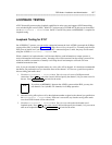
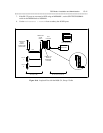
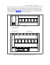
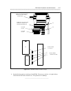
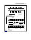
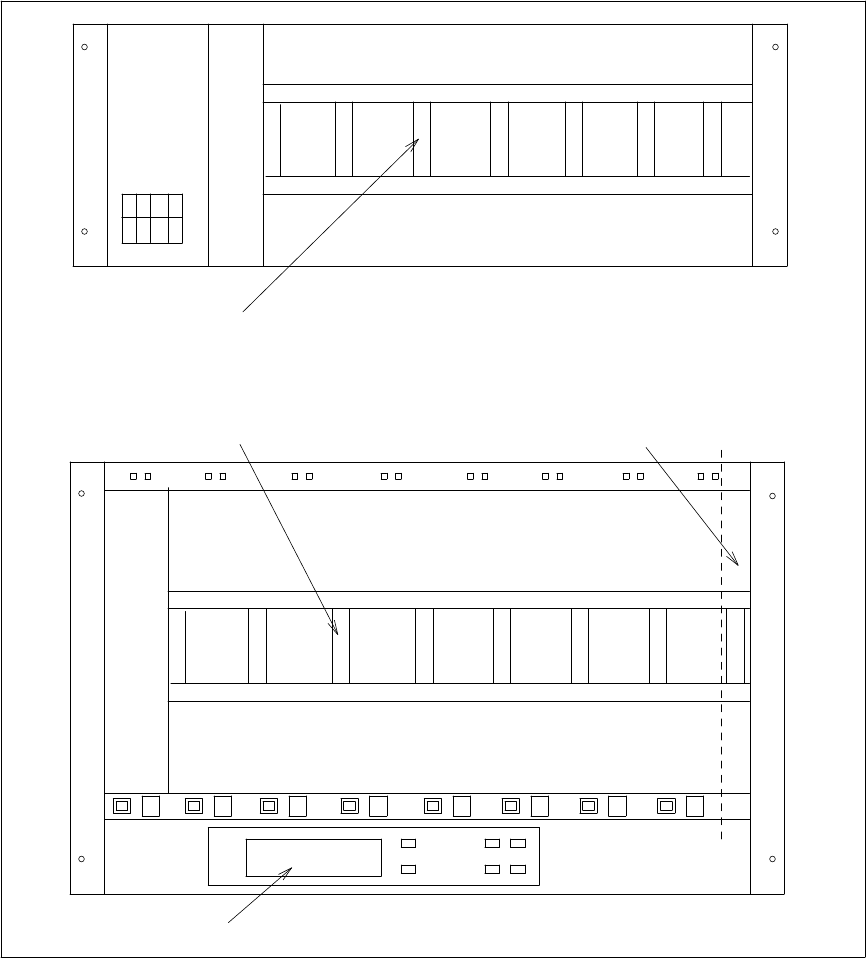
Figure 11-2, Modem Pooling Cabinet with MTDMs (Front View), shows the front of a 105A and a 46A2
mounting. The shared Liquid Crystal Display (LCD) front panel of the 105A is for setting options inside
each modem. The MTDMs require a 46A2 mounting (shown in Figure 11-2). The 7400A data sets require
a 77A mounting (shown in Figure 11-5 Installation procedures for the 7400A are given in the 7400A DSU
Installation and Settings (D-Lead Control) section later in this chapter.
2296A
MODEM
#1
SHARED LCD FRONT PANEL
105A MOUNTING
46A2 MOUNTING
.
.
.
.
.
.
.
.
.
.
.
.
.
.
.
.
.
.
.
.
.
.
.
.
.
.
.
.
.
.
.
.
.
.
.
.
.
.
.
.
.
.
.
.
.
.
.
.
.
.
.
.
.
.
.
.
.
.
.
.
.
.
.
.
.
.
.
.
.
.
.
.
.
.
.
.
.
.
.
.
.
.
.
.
.
.
.
.
.
.
.
.
.
.
.
.
.
.
.
.
.
.
.
.
.
.
.
.
.
.
.
.
.
.
.
.
.
.
.
.
.
.
.
.
.
.
.
.
.
.
.
.
.
.
.
.
.
.
.
.
.
.
.
.
.
.
.
.
.
.
.
.
.
.
.
.
.
.
.
.
.
.
.
.
.
.
.
.
.
.
.
.
.
.
.
.
.
.
.
.
.
.
.
.
.
.
.
.
.
.
.
.
.
.
.
.
.
.
.
.
.
.
.
.
.
.
.
.
.
.
.
.
.
.
.
.
.
.
.
.
.
.
.
.
.
.
.
.
.
.
.
.
.
.
.
.
.
.
.
.
.
.
.
.
.
.
.
.
.
.
.
.
.
.
.
.
.
.
.
.
.
.
.
.
.
.
.
.
.
.
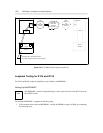
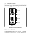
5 6 7 8 1 2 3 4
BACKPLANE CONNECTOR
FOR 2296A (4TH OF 8)
NARROWED SLOT
RESERVED FOR SDU
BACKPLANE CONNECTOR
FOR MTDM (4TH OF 8)
MTDM
#1
Figure 11-2. Modem Pooling Cabinet with MTDMs (Front View)