Chapter 1: Introduction
10 Installing and Configuring the Avaya S8700-Series Server January 2008
Ensuring that the preinstallation tasks are complete
The preinstallation team completes the following tasks. If these tasks are not complete, do not
continue with the installation.
● Verify that the required number of open, customer-supplied, EIA-310D (or equivalent)
standard 19-in. (48-cm) 4-post equipment rack(s) is(are) properly installed and solidly
secured. Ensure that the screws that come with the racks are present. If you use a rack
cabinet, ensure that the cabinet has adequate ventilation.
● Verify that the rail kit to support the server is available to install.
● Verify that the rail kit that is required to support the UPS is installed on the rack or available
to install. For how to install the rails, see the documentation that comes with the rail kit.
● Verify that the equipment racks are grounded per local code. See Job Aid: Approved
Grounds (555-245-772).
● Verify that the customer-provided AC power to the rack is from a nonswitched outlet.
● Verify that cables for theTN2312BP (IPSI) circuit packs are labeled and run from the
control hardware rack to the port networks or that appropriate connectivity is provided.
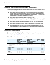
Equipment specifications
The components of the S8700-series Server control network consist of two servers, one or two
Ethernet switches, and two UPSs. The physical specifications for the control network
components are shown in Table 1
.
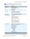
Table 1: Control network components specifications
Component
Dimensions
English
(height x width x depth
in inches
)
Dimensions
Metric
(height x width x depth
in centimeters
)
Height
(u)
Weight
(lb/kg)
Server
S8710, S8720, or
S8730
3.4 x 17.5 x 26 8.6 x 45 x 66 2 60/27
(loaded)
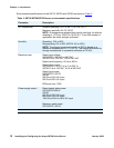
Ethernet switch:
C363T
C364T
1.75 x 17 x 14.4
1.75 x 17 x 14.4
4 x 43 x 37
4 x 43 x 37
1
1
11/5
11/5
UPS:
700 VA
1500 VA
3.5 x 17 x 19
3.5 x 17 x 24
9 x 43 x 48
9 x 43 x 61
2
2
34/15
50/23


