Additional server LED information
Installing and Configuring the Avaya S8700-Series Server January 2008
79
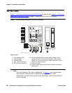
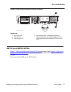
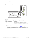
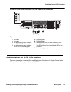
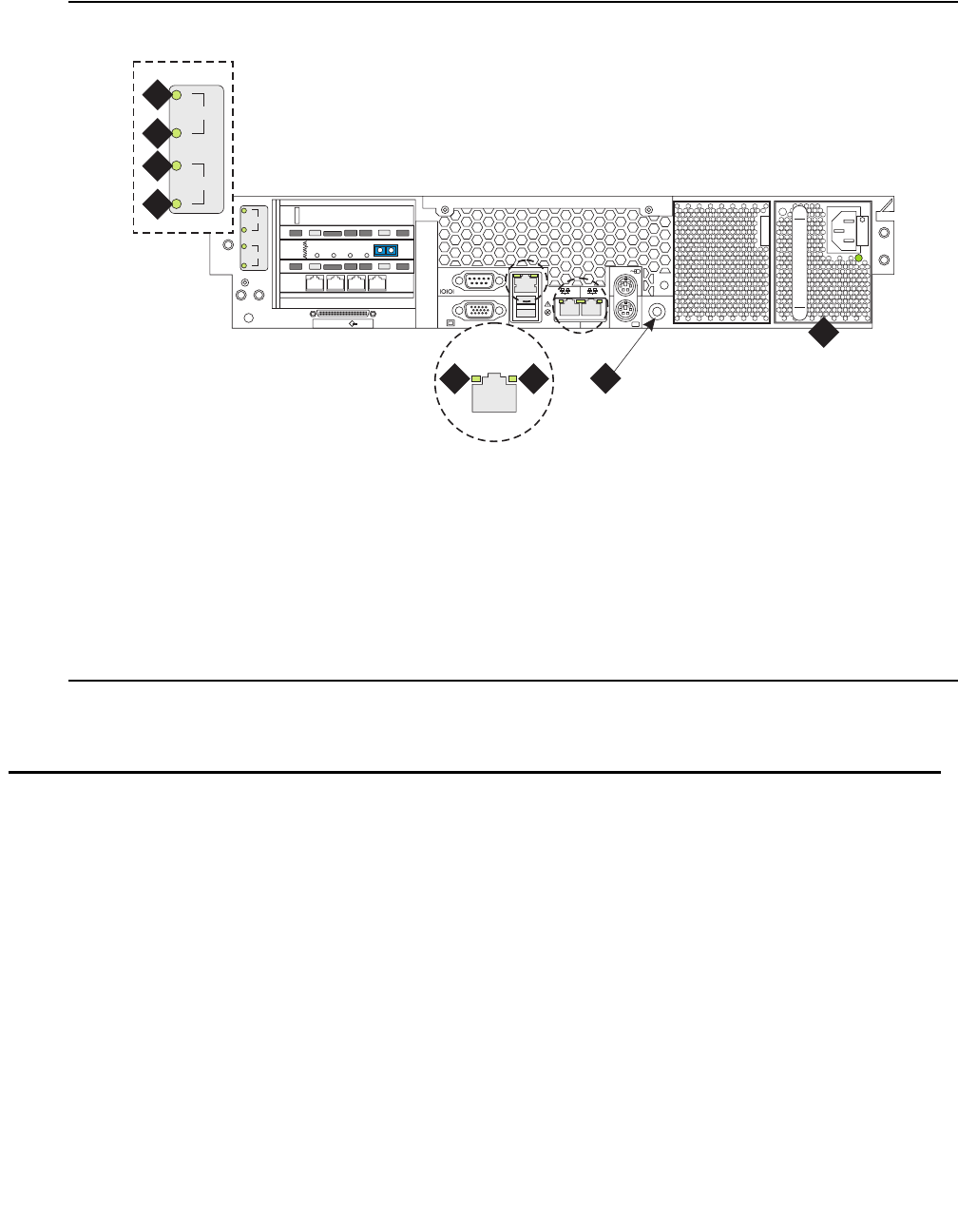
Figure 10: LEDs on the back panel of the S8710 and the S8720 Servers
Additional server LED information
For more information on server LEDs, see Maintenance Procedures for Avaya Communication
Manager, Media Gateways and Servers, 03-300432.
Figure notes:
1. Not used
2. Not used
3. For hardware duplication mode on
the S8710, DAL2 fault (amber)
4. For hardware duplication mode on
the S8710, DAL2 power (green)
5. RJ45 link (green
6. RJ45 link (green)
7. Indicates active when on steady or standby mode
when blinking (blue)
This LED duplicates the Active/Standby LED on the
front panel.
8. Power supply (green)
2
3
iLO
VDCI
1
2
3
133 MGz
100 MGz
100 MGz
UID
2 1
DAL1
DUP
MEMORY
RECEIVE
MODE
LINC
SYNC
TRANS
MODE
LINC
ACTIVE
msds871c KLC 093004
5 6
2
3
1
2
3
4
7
8


