


System Overview 1-11
6\VWHP3 R ZHU6XSSOLHV
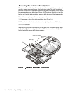
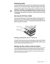
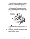
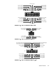
The three redundant power supplies are installed vertically in a row at the front
of the chassis. They can be installed and lifted out of the unit using a handle
that rotates upward. (To release the handle, press on it until it pops up; to
secure it, press it down until it clicks into place.) When fully installed, a power
supply automatically mates with a connector on the PSPB, which lies under
the power supplies. The PSPB controls the power supplies and supplies them
with AC power via the AC routing cable.
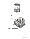
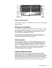
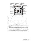
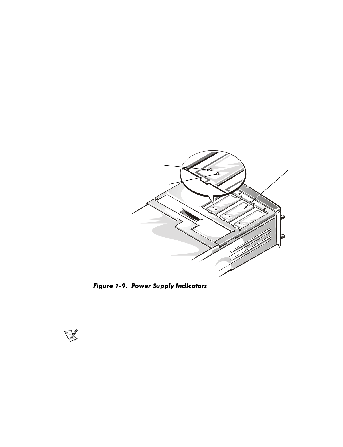
Two indicators on the top of each power supply (see Figure 1-9) signal the
status of the power supply. Both indicators light briefly during initial system
start-up; the green status indicator stays on to show that the power supply is
operating normally. The red fault indicator turns off after initial system start-up
is complete. If it lights any time after system start-up, a fault is indicated in the
power supply and the power supply should be replaced.
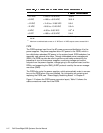
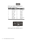
The power supplies can operate from an AC power source of 90 to 265 VAC at
47 to 63 Hz. They provide the DC operating voltages and currents listed in
Table 1-2.
NOTE: The power supplies produce DC voltages only under their loaded
condition. Therefore, when you measure these voltages, the power supplies
must be mated to the PSPB, and the DC power cable harnesses must be
connected to the PSPB and to their corresponding system loads (the system
board, SCSI backplane board, and so forth).
power supplies (3)
green status indicator
(lights when power supply
is functioning normally)
red fault indicator (lights
when a fault is indicated)