


1-18 Dell PowerEdge 6350 Systems Service Manual
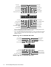
6\VWHP%RDUG/D\RXW
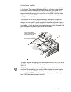
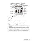
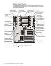
The subsections that follow provide service-related information about the
system board components. Figure 1-19 illustrates the location of important
system board components.
video connector (VGA)
parallel port connector
(PARALLEL [top]) and
serial port connectors (2)
(SERIAL1 and SERIAL2
[bottom])
keyboard and
mouse connectors
(KYBD/MOUSE)
diskette drive
interface
connector (FLOPPY)
battery connector (BATTERY)
Ultra/Narrow SCSI
connector
(SECONDARY SCSI)
speed and
configuration jumpers
front of system board
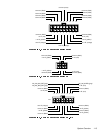
microprocessors (4)
(PROC_1 [top] through
PROC_4)
32-bit PCI connectors
(PCI1 [top] through PCI3)
power input
connector (POWER1)
Ultra2/LVD SCSI
connector (PRIMARY
SCSI-B)
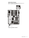
SCSI backplane board
interface cable connector
(BACKPLANE)
server management bus
connector (XSMB_IN)
server management bus
connector (XSMB_OUT)
Dell Remote Assistant
Card connector (SVR_MGT)
PCI activity indicator
connector (PCILEDPNL)
Ultra2/LVD SCSI
connector (PRIMARY
SCSI-A)
power input
connector (POWER2)
power input
connector (POWER3)
64-bit PCI connectors
(PCI4 through PCI7)
memory board
connector
(MEMORY_BD)
chassis intrusion switch
connector (INTRUS)