


1-12 Dell PowerEdge 6350 Systems Service Manual
.
363%
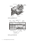
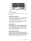
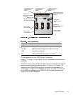
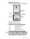
The PSPB receives input from the AC power source and distributes it to the
power supplies. The power supplies return DC power to the PSPB, which in
turn distributes redundant DC power to the system board, SCSI backplane, fan
assembly, and external drive bays. Through embedded server management
(ESM), the PSPB can also be used to perform such tasks as detecting the
presence of one to three power supplies; monitoring voltage and current
outputs from the power supplies, voltage going to the system board, and fan
RPMs; and supporting the SMB_ALERT protocol used by the server manage-
ment bus (SMB).
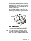
The PSPB sits under the power supplies, which automatically mate to connec-
tors on the PSPB when they are installed. For information on removing and
replacing the PSPB, see “Power-Supply Paralleling Board” in Chapter 4.
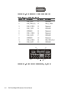
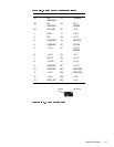
Figure 1-10 shows the PSPB power connector layout; Table 1-3 shows the
cable connections made from the PSPB.
1
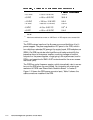
+3.3 VDC +3.23 to +3.46 VDC 18.0 A
+5 VDC +4.90 to +5.25 VDC 38.0 A
+12 VDC +11.40 to +12.60 VDC 9.0 A
–12 VDC –10.80 to –13.20 VDC
0.5
2
A
–5 VDC –4.50 to –5.50 VDC
0.3
2
A
+5 VFP +4.85 to +5.35 VDC 0.4 A
1
Maximum continuous combined load on +5 VDC and +3.3 VDC outputs cannot exceed
240 W.
2
Maximum combined load current on –5 VDC and –12 VDC outputs cannot exceed 0.6 A.