


SAG581126000 System Application Guide
Issue AD, November 23, 2009 Spec. No. 581126000 (Model 700
NVBA)
Page 18 of 123
This document is property of Emerson Network Power, Energy Systems, North America, Inc. and contains confidential and proprietary information owned by Emerson Network Power, Energy
Systems, North America, Inc. Any copying, use, or disclosure of it without the written permission of Emerson Network Power, Energy Systems, North America, Inc. is strictly prohibited.
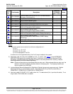
9) Order as required additional options per Lists 29 and 93.
10) Order as required any additional accessories described under
ACCESSORY DESCRIPTIONS.
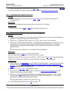
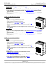
List 4: “Distribution Only” Option for Lists 2 or 5
Features
♦ Provides components needed to convert one
List 2 or List 5 bay from “power and distribution” to
“distribution only”.
Restrictions
A Module Mounting Assembly cannot be mounted in a bay when List 4 is installed.
Ordering Notes
1) Order one List 4 for each
List 2 or List 5 being ordered for distribution only.
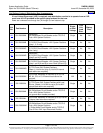
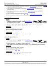
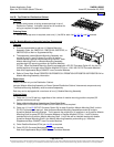
List 5: Supplemental Bay Common Equipment (Power and Distribution)
(located away from Main Bay)
Features
♦ Provides common equipment for one remote “power and distribution” bay rated for up to 2000 amperes of
distribution. Includes inter-bay communications cabling.
♦ Accepts one (1) Distribution Cabinet (options are 1-Row, 2-Row, 3-Row, or 4-Row cabinet).
♦ Accepts one (1) Module Mounting Assembly. The Module Mounting Assembly can consist of one (1), two
(2), three (3), or four (4) factory interconnected 8-position Module Mounting Shelves. Each Module
Mounting Shelf in a Module Mounting Assembly provides eight (8) mounting positions for Rectifier
Modules (PCUs).
or
Can be configured for “distribution only” (no Module Mounting Assembly).
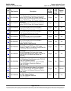
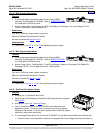
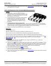
Restrictions
Order maximum of one (1)
List 2 or List 5 per Power System.
Cannot be used when List 2 is ordered. Order List 2 or List 5, not both.
Supplemental Bays DO NOT accept Converter Modules. DO NOT order List
60 or 62 for Supplemental Bays.
Interbay power cabling is not included, and must be separately provided per site requirements.
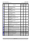
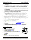
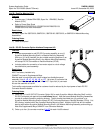
Ordering Notes
1) Order a relay rack per '
Relay Racks' under ACCESSORY DESCRIPTIONS. If required, order Relay Rack
Transition Plates per '
Transition Plates to Mount Relay Rack P/N 543156 on Top of GNB Absolyte IIP
Batteries' under ACCESSORY DESCRIPTIONS. A ship loose option is available, as described in 'Relay
Racks' under ACCESSORY DESCRIPTIONS.
2) Order one (1) List
21, 22, 23, or 24 Distribution Cabinet.
3) Order up to four (4) Distribution Bus Panels as required per '
Distribution Bus Arrangements' and the
capacity of the Distribution Cabinet ordered.
4) Order one (1) List
30 (interface components for one (1) Module Mounting Assembly). Order a Module
Mounting Assembly per PD588705101/PD588705102/PD588705103/PD58805104. List 30 is factory
connected to the Module Mounting Assembly ordered.
or
Order Supplemental Bay 'Distribution Only' option per List
4.
5) Order Rectifier Modules (PCUs) per List
50 as required.
Home