


System Application Guide SAG581126000
Spec. No. 581126000 (Model 700
NVBA) Issue AD, November 23, 2009
Page 81 of 123
This document is property of Emerson Network Power, Energy Systems, North America, Inc. and contains confidential and proprietary information owned by Emerson Network Power, Energy
Systems, North America, Inc. Any copying, use, or disclosure of it without the written permission of Emerson Network Power, Energy Systems, North America, Inc. is strictly prohibited.
Wiring Components
Load Distribution Wire Sizes and Lugs Selection
Features
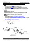
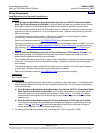
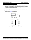
♦ When Distribution Bus Modules Using Bullet Nose-Type Devices (TPS/TLS Fuses and/or Bullet
Nose-Type Circuit Breakers) are Provided: Lug-terminated load leads are connected to the individual
load busbars located on the Distribution Bus Module and the respective distribution ground busbar.
The individual load busbars provide 1/4-20 threaded holes for installation of customer-provided two-hole
lugs that have 5/8 inch centers and 1/4 inch bolt clearance holes. Customer must provide lug mounting
bolts and hardware.
The distribution ground busbar provides 1/4-20 studs for installation of the same type of customer-
provided lugs. Customer must provide lug mounting hardware.
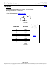
Refer to the illustrations under the
LIST DESCRIPTIONS for a dimensional drawing.
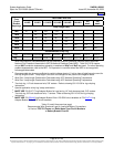
Maximum size of wire to be connected to a single fuseholder/circuit breaker position is 2 AWG. For wiring
up to 350 kcmil, see
Table 11 (Special Application Crimp Lug / Strap Combination), or see the following
part numbers in
ACCESSORY DESCRIPTIONS for available adapter busbars: 514717, 534449, and
514714.
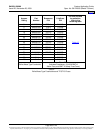
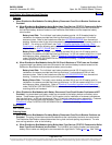
♦ When Distribution Bus Modules Using GJ/218 Circuit Breakers or TPH Fuses are Provided: Lug-
terminated load leads are connected to the individual load busbars located on the Distribution Bus
Module and the respective distribution ground busbar.
The individual load busbars provide 3/8-16 captive nuts for installation of customer-provided two-hole lugs
that have 1 inch centers and 3/8 inch bolt clearance holes. Customer must provide lug mounting bolts
and hardware.
The distribution ground busbar provides 3/8-16 captive nuts for installation of the same type of customer-
provided lugs. Customer must provide lug mounting bolts and hardware.
Refer to the illustrations under the
LIST DESCRIPTIONS for a dimensional drawing.
Restrictions
See 'Features' above.
Ordering Notes
1) The rating of the distribution device determines the load lead wire size requirement. The Distribution Bus
Module ordered determines the lug hole size and spacing requirements. For wire size and lug selection;
refer to the following.
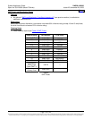
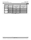
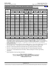
a) When Distribution Bus Modules Using Bullet Nose-Type Devices (TPS/TLS Fuses and/or Bullet
Nose-Type Circuit Breakers) are Provided: The individual load busbars and associated ground
busbar are designed to accommodate the lugs listed in Tables
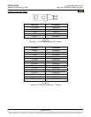
9 and 11. Use Table 12 to select
recommended load distribution wire sizes and lugs for various loop lengths per fuse/circuit breaker
ampere rating.
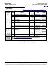
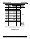
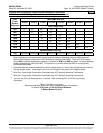
b) When Distribution Bus Modules Using GJ/218 Circuit Breakers or TPH Fuses are Provided:
The individual load busbars and associated ground busbar are designed to accommodate the lugs
listed in Table
10. Use Table 13 to select recommended load distribution wire sizes and lugs for
various loop lengths per fuse/circuit breaker ampere rating.
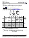
2) For other available lugs and hardware, refer to drawings 031110100 through 031110300.
Home