


System Application Guide SAG581126000
Spec. No. 581126000 (Model 700
NVBA) Issue AD, November 23, 2009
Page 95 of 123
This document is property of Emerson Network Power, Energy Systems, North America, Inc. and contains confidential and proprietary information owned by Emerson Network Power, Energy
Systems, North America, Inc. Any copying, use, or disclosure of it without the written permission of Emerson Network Power, Energy Systems, North America, Inc. is strictly prohibited.
Replacement Cables
Ordering Notes
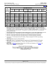
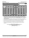
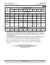
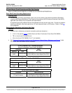
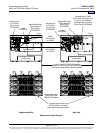
1) Refer to the following table and illustration.
Item Part Number / Description
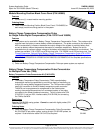
Standard External Alarm
Interconnect Cable (cannot be
used with List 71):
One 15 ft. cable is provided with List 1. For a replacement cable,
order P/N 514327. Also available is P/N 514380 (60 ft. cable).
Provides pre-assembled cable and mating connector for connecting
the MCA external alarm connector to customer circuits.
Connects to J8 on the MCA Main Controller circuit card P/N 534868
located in the Main Bay Distribution Cabinet, and provides
unterminated 28 AWG leads for splicing to customer leads.
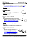
Bay Module Mounting Shelf
Interface Circuit Card to MCA
Interconnect Cable:
P/N 509071
Provides pre-assembled cable and mating connectors for connecting
the Bay Module Mounting Shelf Interface circuit card to the MCA (via
the “Interconnect/Inhibit” circuit card).
Connects between the Module Mounting Shelf Interface circuit card
P/N 535250 located in the Bay Distribution Cabinet and the
“Interconnect/Inhibit” circuit card located in the same Distribution
Cabinet.
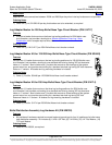
Bay Internal
'Rectifier Module Control'
Interconnect Cable:
P/N 529120
Provides pre-assembled cable and mating connectors for connecting
the Bay Module Mounting Shelf Interface circuit card to the top most
Module Mounting Shelf.
Connects between the pigtail located on Module Mounting Shelf
Interface circuit card P/N 535250 located in the Bay Distribution
Cabinet and the connector exiting the top of the topmost Module
Mounting Shelf.
Note that subsequent Module Mounting Shelves located within the
same bay are interconnected via the shelf internal wiring harness.
Connect the mating connector of the cable exiting the bottom of one
Module Mounting Shelf with the connector exiting the top of the shelf
installed below it.
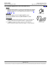
Bay-to-Bay
'Distribution Control'
Interconnect Cable:
A 6 ft. cable is provided with List 2. For a replacement cable, order
P/N 514334.
A 25 ft. cable is provided with List 5. For a replacement cable, order
P/N 100916.
Provides pre-assembled cable and mating connectors for connecting
the alarm, reference, and control leads of the Supplemental Bay
distribution to those of the Main Bay distribution (and to the MCA).
Connects between J1 on “Interconnect/Inhibit” circuit card 509532
located within the Main Bay Distribution Cabinet and J2 on
“Interconnect/Inhibit” circuit card 509532 located within the
Supplemental Bay Distribution Cabinet.
Home