


System Application Guide SAG581126000
Spec. No. 581126000 (Model 700
NVBA) Issue AD, November 23, 2009
Page 49 of 123
This document is property of Emerson Network Power, Energy Systems, North America, Inc. and contains confidential and proprietary information owned by Emerson Network Power, Energy
Systems, North America, Inc. Any copying, use, or disclosure of it without the written permission of Emerson Network Power, Energy Systems, North America, Inc. is strictly prohibited.
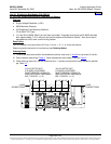
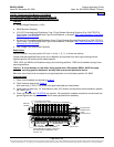
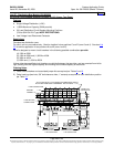
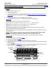
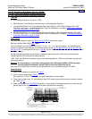
List CF: Distribution Bus Module (P/N 509647)
(8) GJ/218 Circuit Breaker System Positions w/LVLD (Lower Two Rows)
Features
♦ Single Voltage Distribution (+24V)
♦ 1,000A Maximum Capacity (500A per side)
♦ (8) Load Distribution Circuit Breaker Mounting Positions
(100 to 600A GJ/218-Type) NOTE RESTRICTIONS.
♦ Low Voltage Load Disconnect Contactor
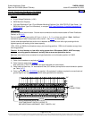
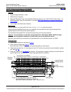
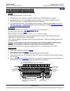
Restrictions
Occupies two distribution rows.
For use in a 2-, 3-, or 4-bus row cabinet. Must be installed in bus positions A and B (rows 1 and 2), or B and
C (rows 2 and 3). See also
List CE for similar application in bus positions C and D (rows 3 and 4).
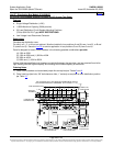
Panel is designed to mount circuit breakers in the following possible combinations per side:
(4) 100A to 250A
(2) 100A to 250A and (1) 300A or 400A
(2) 300A or 400A
(1) 600A and (1) 100A to 250A
Unless otherwise specified circuit breakers are divided between the two sides, and are mounted from left to
right, starting with the highest capacity and working to the lowest capacity on each side.
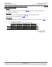
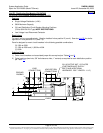
Ordering Notes
1) Order circuit breakers and associated jumper kits as required per Tables
5 and 6.
2) Order load lugs (two hole, 3/8” bolt clearance hole, 1” centers) as required for each distribution position
per Table
10.
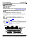
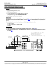
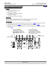
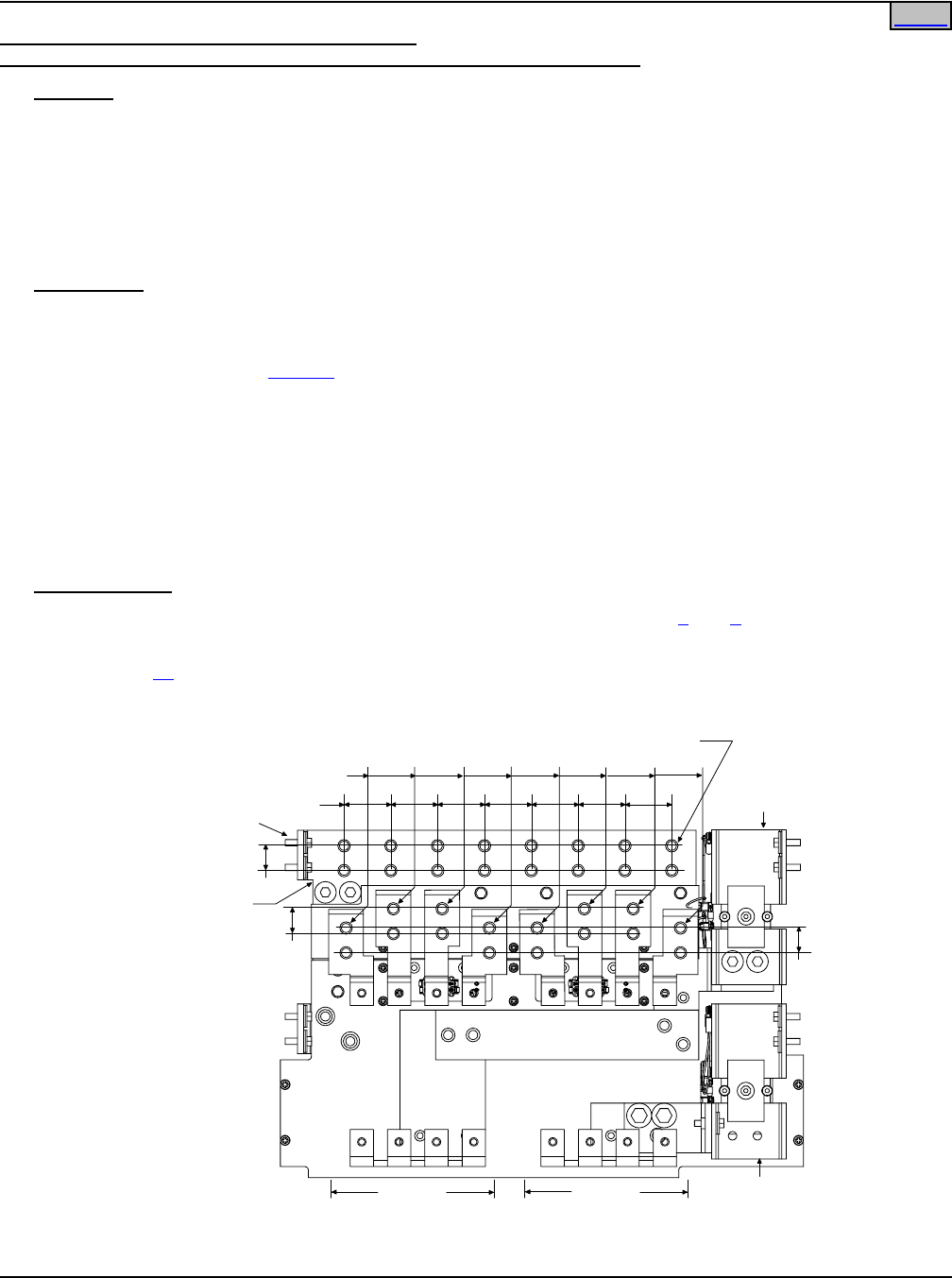
1"
LOAD CONNECTIONS
1-7/8"
1"
LOAD RETURN
CONNECTIONS
1"
LOADS
CONTROLLED BY UPPER
LVD CONTACTOR
LOADS
CONTROLLED BY LOWER
LVD CONTACTOR
UPPER LVD
CONTACTOR
LOWER LVD
CONTACTOR
3/8-16 CAPTIVE NUT, 32 PLACES(CUSTOMER MUST SUPPLY
BOLTS AND ADDITIONAL HARDWARE. BOLT LENGTH: 1-1/4")
GROUND
BUSBAR
Home