


System Application Guide SAG581126000
Spec. No. 581126000 (Model 700
NVBA) Issue AD, November 23, 2009
Page 59 of 123
This document is property of Emerson Network Power, Energy Systems, North America, Inc. and contains confidential and proprietary information owned by Emerson Network Power, Energy
Systems, North America, Inc. Any copying, use, or disclosure of it without the written permission of Emerson Network Power, Energy Systems, North America, Inc. is strictly prohibited.
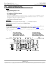
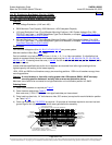
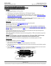
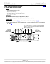
List LB: Distribution Bus Module (Part No. 513807)
(8) +24V Fuse/Circuit Breaker System Positions w/LVD and
(8) –48V Fuse/Circuit Breaker Subsystem Positions
Features
♦ Dual Voltage Distribution (+24V and -48V)
♦ 500A Maximum Total Capacity, 200A Maximum –48V Subsystem Capacity
♦ (8) Load Distribution Fuse / Circuit Breaker Mounting Positions (+24V System Voltage) (3 to 100A
TPS/TLS-Type Fuses / 1 to 250A Bullet Nose Type Circuit Breakers, or accepts “
GMT Load Distribution
Fuse Block Assembly Kit (P/N 514432)”.
♦ (8) Load Distribution Fuse / Circuit Breaker Mounting Positions (-48V Subsystem Voltage) (3 to 100A
TPS/TLS-Type Fuses / 1 to 250A Bullet Nose Type Circuit Breakers, or accepts “
GMT Load Distribution
Fuse Block Assembly Kit (P/N 514432)”.
♦ Low Voltage System Load Disconnect Contactor
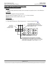
Restrictions
Limit one dual voltage bus (List
JA, JB, JC, JD, KA, LB, LC) per power system.
Must be installed in Main Bay (
List 1) only.
Can be installed in any bus position A-D (row 1-4) of a 1-, 2-, 3- or 4-bus row cabinet. If a distribution bus
module is mounted directly beneath, that module must be a List
AA, AE, AK, AM, BA, CA, CF, EA, GB, NA,
NB, RA, or RB. If ordering more than one (1) List 60, List LB must be installed in bus position A (row 1) of the
distribution cabinet.
Unless otherwise specified fuses and/or circuit breakers are mounted from left to right, starting with the
highest capacity and working to the lowest capacity.
125A, 150A, and 200A circuit breakers occupy two mounting positions. 250A circuit breakers occupy three
mounting positions.
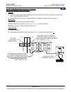
Caution:
A circuit breaker or fuse with a rating greater than 150 amperes SHALL HAVE an empty
mounting position between it and any other overcurrent protective device.
Maximum size of wire to be connected to a single fuseholder or circuit breaker position is 2 AWG.
Ordering Notes
1) Order circuit breakers as required per
Table 7.
2) Order fuses as required per
Table 8.
Also order one (1) P/N 117201 bullet nose-type fuseholder per fuse ordered.
3) Order load lugs (two hole, 1/4” bolt clearance hole, 5/8” centers) as required for each distribution position
per Table
9 or 11.
4) Order lug hardware kit,
P/N 520332 as required. Kit provides all hardware required to connect load and
ground lugs for four (4) positions of a bullet nose-type distribution assembly.
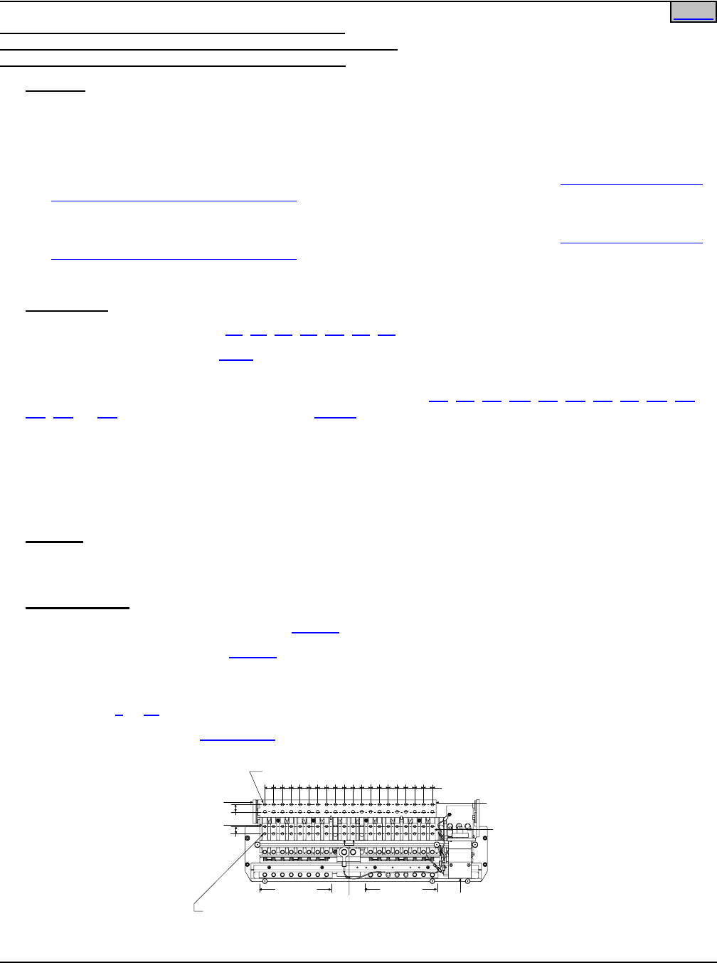
LOAD RETURN
CONNECTIONS
+24V LOAD
CONNECTIONS
(SYSTEM)
1/4-20 STUD, 40 PLACES
(CUSTOMER MUST SUPPLY ADDITIONAL HARDWARE)
GROUND
BUSBAR
-48V LOAD
CONNECTIONS
(SUBSYSTEM)
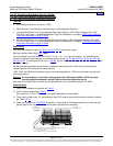
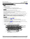
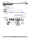
-48V LOADS
(SUBSYSTEM)
+24V LOADS
(SYSTEM)
5/8"
5/8"
1/4-20 THREADED HOLE, 32 PLACES
(CUSTOMER MUST SUPPLY LUG BOLTS
AND ADDITIONAL HARDWARE. BOLT LENGTH: 3/4")
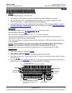
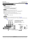
-48V INPUT
(Factory
Connection)
3/4"
LVD
CONTACTOR
Home