System Application Guide SAG581126000
Spec. No. 581126000 (Model 700
NVBA) Issue AD, November 23, 2009
Page 83 of 123
This document is property of Emerson Network Power, Energy Systems, North America, Inc. and contains confidential and proprietary information owned by Emerson Network Power, Energy
Systems, North America, Inc. Any copying, use, or disclosure of it without the written permission of Emerson Network Power, Energy Systems, North America, Inc. is strictly prohibited.
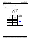
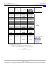
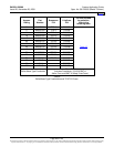
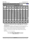
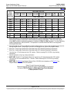
to select recommended battery wire sizes and lugs for various loop lengths per battery
disconnect fuse/circuit breaker ampere rating. Table
13 may be used to select two-hole lugs
with 3/8 inch bolt clearance holes and 1 inch centers for the battery return busbar.
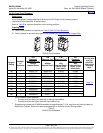
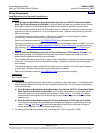
b) When Distribution Bus Modules Using GJ/218 Circuit Breakers or TPH Fuses are Provided:
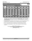
The individual input battery busbars and associated battery return busbar are designed to
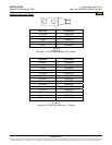
accommodate the lugs listed in Table
10. Use Table 13 to select recommended battery wire sizes
and lugs for various loop lengths per battery disconnect fuse/circuit breaker ampere rating.
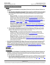
2) When Distribution Bus Modules with Battery Disconnect Fuse/Circuit Breaker Positions are NOT
Provided: Battery wire size and lug requirements are determined by site requirements. For wire size
and lug selection; refer to the following.
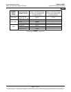
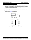
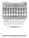
The battery busbars are designed to accommodate the lugs listed in Tables
9 and 10. Use Table 13
to select recommended battery wire sizes and lugs for various loop lengths per required battery
branch circuit ampere rating. Table
12 may be used to select two-hole lugs with 1/4 inch bolt
clearance holes and 5/8 inch centers.
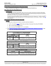
Note: Lists RA, RB, RC, RD, and RE do not provide 1/4-20 captive nuts on the battery busbar; only
3/8-16 captive nuts are furnished.
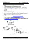
3) For other available lugs and hardware, refer to drawings 031110100 through 031110300.
Home


