SAG581126000 System Application Guide
Issue AD, November 23, 2009 Spec. No. 581126000 (Model 700
NVBA)
Page 70 of 123
This document is property of Emerson Network Power, Energy Systems, North America, Inc. and contains confidential and proprietary information owned by Emerson Network Power, Energy
Systems, North America, Inc. Any copying, use, or disclosure of it without the written permission of Emerson Network Power, Energy Systems, North America, Inc. is strictly prohibited.
ACCESSORY DESCRIPTIONS
Relay Racks
Features
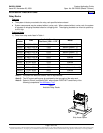
♦ The system is factory mounted to the relay rack specified when ordered.
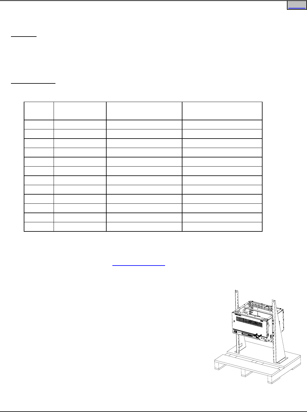
♦ System components may be ordered without a relay rack. When ordered without a relay rack, the system
is mounted on shipping brackets bolted to a shipping skid. The shipping brackets can mount a system up
to 20U high.
Ordering Notes
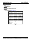
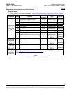
1) Order from relay racks listed in Table 1.
Part
Number
Size
Available Mounting
Positions (1RU = 1-3/4”)
Notes
543151 25.656”H x 23”W 13RU Welded (Notes 1, 3)
543152 27.406”H x 23”W 14RU Welded (Notes 1, 3)
543153 36.156”H x 23”W 19RU Welded (Notes 1, 3)
543154 39.656”H x 23”W 21RU Welded (Notes 1, 3)
543155 43.156”H x 23”W 23RU Welded (Notes 1, 3)
543156 51.906”H x 23”W 28RU Welded
543157 71.156”H x 23”W 39RU Welded
543161 6’0”H x 23”W 37RU Welded
543162 7’0”H x 23”W 45RU Welded
541340 7’0”H x 23”W 45RU Seismic (Notes 1, 2, and 3)
543163 7’6”H x 23”W 48RU Welded
543164 8’0””H x 23”W 51RU Welded
Note 1: Complies with Bellcore Seismic Zone 4 requirements.
Note 2: The DC output cabling may be restricted by the top angle of the relay rack.
Note 3: Seismic (Zone 4) compliant ONLY when system DOES NOT contain any of the
following components:
List 93 Battery Tray
Table 1
Available Relay Racks
Ship Loose Option
Home


