


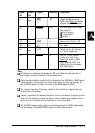
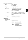
Signal
Return
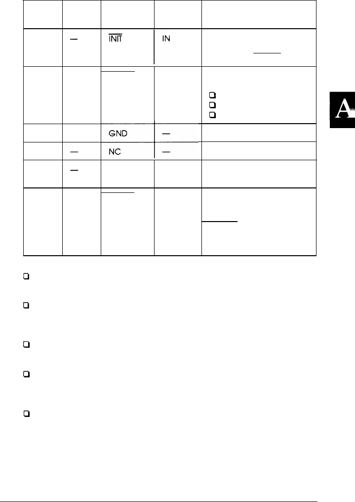
Pin Pin
31
32
33
34
35
36
-
-
-
Signal
Direction Description
ERROR
OUT
+5V
-
SLCTIN
IN
I I I I
When this signal goes
LOW, the printer controller
ignores the STROBE signal.
This level goes LOW when
the printer is:
0
out of paper
0
in error state
0
off line
Same as for Pins 19 - 30.
Not used.
Pulled up to +5V through
3.3 Kohm resistance.
The DC 1/DC3 control
codes are valid only
when this signal is HIGH
(SLCTIN set to OFF). This
setting can be changed
with SelecType.
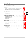
Note:
Cl
All interface conditions are based on TTL level. Both the rise and fall of
each signal must be less than 0.2 microseconds.
0
Data transfer must be carried out by observing the ACKNLG or BUSY signal.
(Data transfer to this printer can be carried out only after the receipt of
the ACKNLG signal or when the level of the BUSY signal is LOW.)
0
The column heading ‘Direction’ refers to the direction of signal flow as
viewed from the printer.
0
‘Return’ denotes the twisted-pair return to be connected at signal ground
level. For the interface wiring, be sure to use a twisted-pair cable for each
signal and to complete the connection on the return side.
0
The ACKNLG pulse width varies or is permanently set to HIGH, depending
on the setting of the BUSY DELAY option in SelecType Level 2.
Technical Specifications
A-11