


Handshaking
The printer’s serial interface can use DTR (Data Terminal
Ready) signal levels and XON/XOFF communication protocols
either separately or in combination.
When the vacant area for data in the input buffer drops to 128
bytes, the printer outputs an XOFF code or sets the DTR signal
level to low (MARK), indicating that the printer cannot receive
more data.
Once the vacant area for data in the buffer recovers to 256
bytes, the printer outputs an XON code or sets the DTR flag to
high (SPACE), indicating that the printer is again ready to
receive data.
Error handling
An * character is printed if a parity error, framing error, or
overrun error is detected.
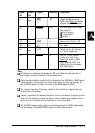
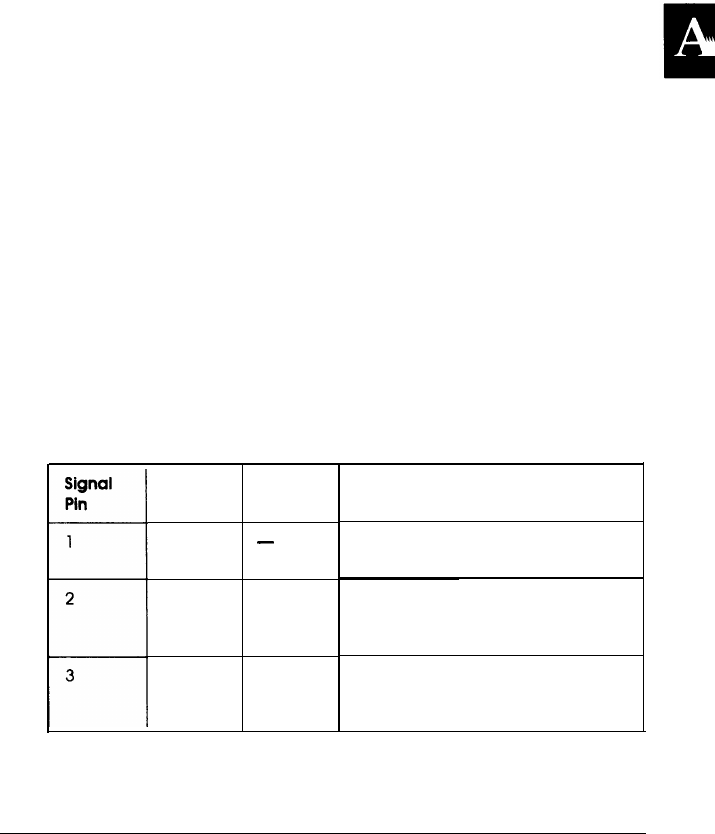
Serial interface pin assignments
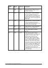
The serial interface connector pin assignments and a
description of the interface signals are shown in the table
below. The direction of signals is given relative to the printer.
Signal
-4
Pin
1
Signal
Direction
FG
-
TXD OUT
RXD
IN
Description
This line is connected to the printer
chassis.
Transmits data. This pin transmits
serial data from the printer to the
computer.
Received data. This pin transmits
serial data from the computer to
the printer.
Technical Specifications A-13