


Stylus C40UX/C40SX/C20UX/C20SX Revision A
Appendix Connector Summary 100
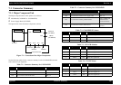
7.1 Connector Summary
7.1.1 Major Component Unit
The Major component units of this printer are as follows.
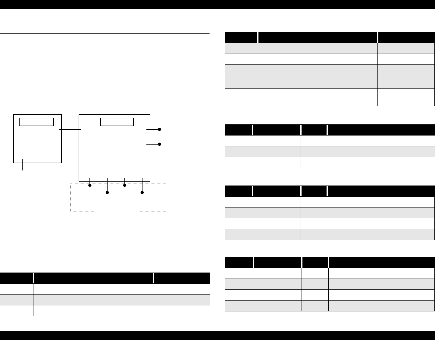
Main Board (C413MAIN or C413MAIN-B)
Power Supply Board (C417/PSE)
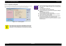
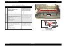
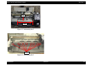
The figure below shows how these components connect.
Figure 7-1. Connection of the Major Components
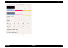
See the following tables for the connector summary for the C413MAIN/B board and
each connector’s pin alignment.
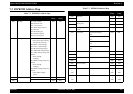
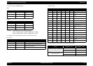
Table 7-1. Connector Summary for C413MAIN/B
Connector Function Table to refer to
CN4 For connection with the HP/PE/IC/sensor Table 7-2
CN12 For connection with the CR motor Table 7-3
CN7 For connection with the PF motor Table 7-4
C417PSB/PSE
CN2 CN2
CN9
Print Head
AC Power
CN12
CR Motor
Printer Mechanism
HP/PE/IC
CN7
PF Motor
CN4
CN1
Parallel I/F
(C413MAIN)
CN3
C413MAIN/B
USB I/F
(C413MAIN-B)
CN9 For connection with the Print Head Table 7-5
CN2 For connection with the Power supply board Table 7-6
CN1 For connection with the parallel interface
Refer to “IEEE-1284
Parallel Interface
(Forward Channel)”
CN3 For connection with the USB interface
Refer to “1.3.1 USB
INterface”
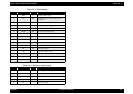
Table 7-2. CN4-HP/PE/IC Sensor
Pin Signal Name I/O Function
1 SIG In Sensor detect signal
2 GND --- Ground
3 VCC --- Sensor Power Supply
Table 7-3. CN12-CR Monitor
Pin Signal Name I/O Function
1 CRA Out Phase drive signal (A)
2 CRB Out Phase drive signal (B)
3 CR-A Out Phase drive signal (-A)
4 CR-B Out Phase drive signal (-B)
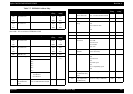
Table 7-4. CN3-PF Motor
Pin Signal Name I/O Function
1 PFA Out Phase drive signal (A)
2 PFB Out Phase drive signal (B)
3 PF-A Out Phase drive signal (-A)
4 PF-B Out Phase drive signal (-B)
Table 7-1. Connector Summary for C413MAIN/B
Connector Function Table to refer to