


Stylus C40UX/C40SX/C20UX/C20SX Revision A
Operating Principles Electrical Circuit Operating Principles 41
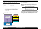
2.2 Electrical Circuit Operating Principles
The electric circuit of the Stylus C40UX/C40SX/C20UX/C20SX consists of the
following boards.
Main board: C413 MAIN (USB)
C413 MAIN-B (Parallel)
Power supply board: C417 PSB/PSE Board
NOTE: The C413MAIN/-B board is used for the product in the first mass
production and it will be changed to C413MAIN-C/-D board at an early
date. The major difference is that a single chip which integrates the
ASIC, CPU and PROM is used on the C413MAIN-C/-D board.
C413 MAIN-C (USB)
C413 MAIN-B (Parallel)
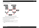
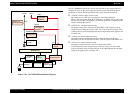
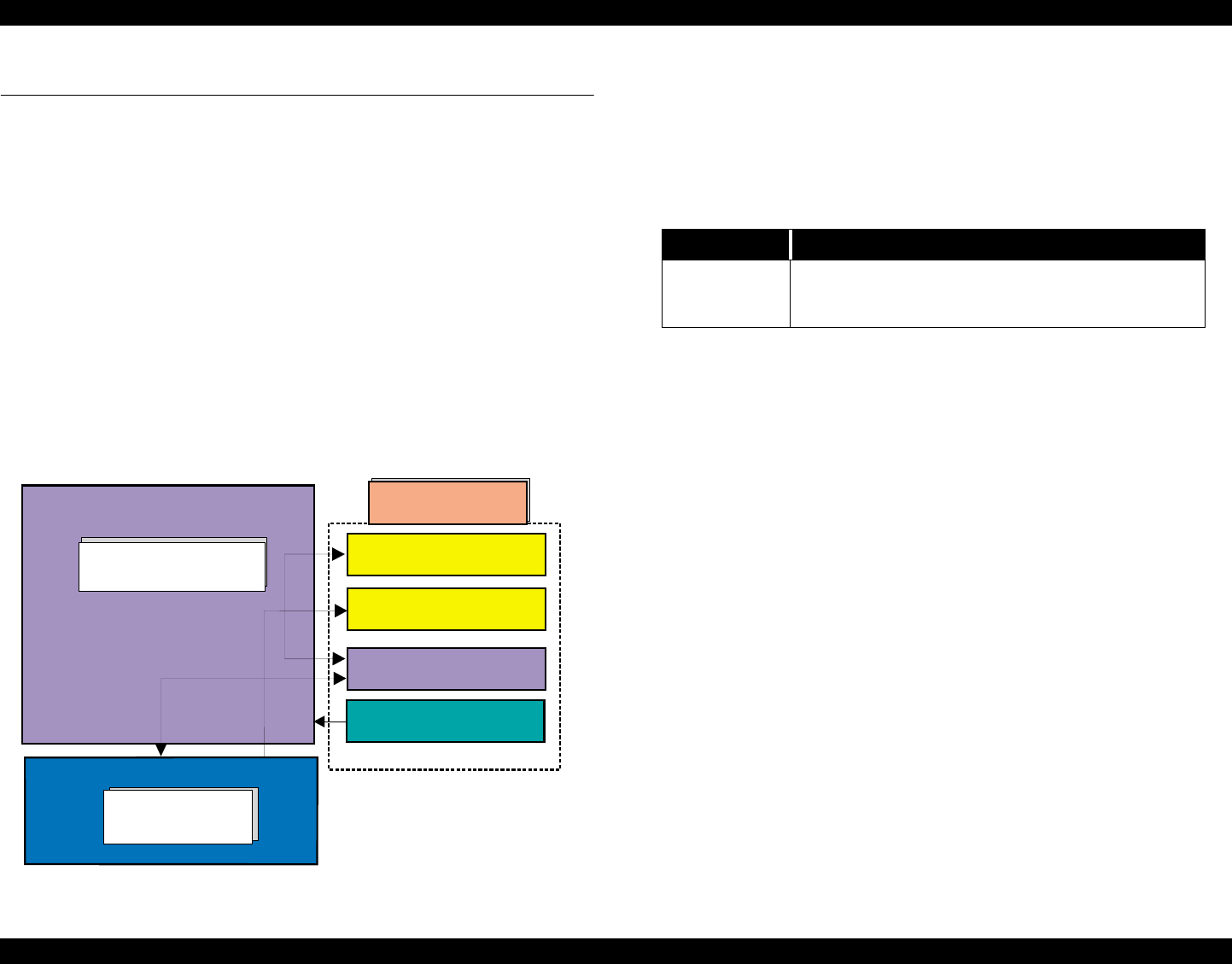
This section provides operating principles of C413 MAIN/B Board and C417 PSB/PSE
Board. Refer to Figure 2-19 for the major connection of the each boards and their
roles.
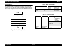
Figure 2-19. Electric Circuit
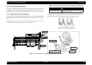
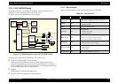
2.2.1 C417 PSB/PSE board
The power supply boards of Stylus C40UX/C40SX/C20UX/C20SX use a RCC
(Ringing Chalk Converter) circuit, which generates +36VDC for drive line and
+5VDC for logic line to drive the printer. The application of the output voltage is
described below.
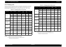
Table 2-7. Application of the DC Voltages
AC voltage input from AC inlet first goes through filter circuit that removes high
frequency components and is then converted to DC voltage via the rectifier circuit and
the smoothing circuit. DC voltage is then lead to the switching circuit and FET Q1
preforms the switching operation. By the switching operation of the primary circuit,
+36VDC is generated and stabilized at the secondary circuit.
C413 MAIN-A/B Board
Printer Mechanism
CR Motor
PF Motor
Print Head
HP/PE/IC Sensor
+36VDC
+5VDC
C417 PSB/PSE
Board
Voltage Application
+36VDC
• Motors (CR Motor, PF Motor)
• Printhead common voltage
• Printhead nozzle selector 36V drive voltage