


Stylus C40UX/C40SX/C20UX/C20SX Revision A
Operating Principles Overview 32
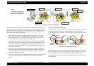
Transfer the PF motor drive to LD roller
PF Motor Pinion Gear (CW)
→ Spur Gear 60 (PF Roller) (CCW) →
Spur Gear
10.8
(CCW)
→
Combination Gear 18, 28 (CW)
→
Spur Gear
27.2 (CCW)
→ Spur Gear
25.6 (CW) →
Change Laver rotates (CW)
→
Combination Gear 16, 32 (CCW)
→
Spur Gear 35.2 (CW) (include the clutch mechanism) →
LD Roller (CW)
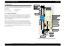
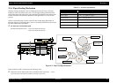
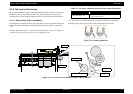
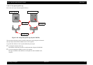
Following Figure 2-9 shows the PF motor drive transmission path to the LD roller unit
built in the ASF unit. The LD roller is assembled on the same shaft that the Spur gear
35.2 is assembled.
Figure 2-10. PF motor drive transmission path
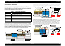
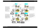
When the PF motor torque is switched to the ASF unit side by the clutch mechanism,
the function of the ASF mechanism varies depending on the rotational direction of the
PF motor, as shown in the table below.
Table 2-3. ASF unit function & PF Motor rotational direction
(*1): The PF Motor rotational direction = seen from the right side of the printer.
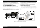
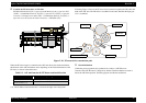
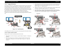
Clutch Mechanism
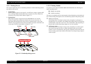
Unlike the previous products, this product dose not have a ASF HP sensor.
Instead of the ASF HP sensor, Change lever and the Clutch mechanism are used to
detect the ASF home position. Following figures describe the mechanism.
Spur Gear 35. 2
Combination
Gear 35. 2
Spur Gear 25. 6
Spur Gear 27. 2
Combination Gear 18, 28
Spur Gear 10, 8
Change Lever
Directions Corresponding Functions
Clockwise (*1)
• Picks up and loads paper
Counterclockwise (*1)
• Release the DE lever & Clutch mechanism