


Stylus C40UX/C40SX/C20UX/C20SX Revision A
PRODUCT DESCRIPTION INTERFACE 13
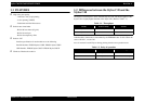
1.4 INTERFACE
Interface specification for each model are as the following.
Parallel Interface :EPSON Stylus C40SX .EPSON Stylus C20SX
USB Interface :EPSON Stylus C40UX .EPSON Stylus C20UX
*This printer interface as standard.
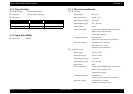
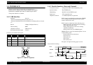
1.4.1 USB Interface
Standard : based on
“Universal Serial Bus Specifications Revision 1.1”
“Universal Serial Bus Device Class Definition for Printing Devices Version
1.1”
Bit rate : 12Mbps (Full Speed Device)
Data encording : NRZI
Adaptable connector : USB Series B
Recommended cable length : 2 meters
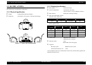
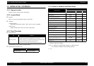
Connect er pin assinment and signals:
Figure 1-3. USB Pin Assignment
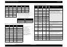
1.4.2 Parallel Interface (Forward Channel)
Transmission mode : 8 bit parallel, IEEE-1284 compatibility mode
Synchronization : By STROBE pulse
Handshaking : By BUSY and ACKNLG signal
Signal level : TTL compatible level
Adaptable connector : 57-30360(amphenol) or equivalent
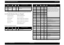
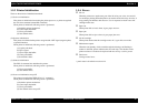
BUSY signal is set high before setting either -ERROR
low or PE high and held high until all these signals
return to their inactive state.
BUSY signal is at high level in the following cases.
-During data entry (see Data transmission timing)
-When input data buffer is full
-During -INIT signal is at low level or during
hardware initialization
-During printer error (See -ERROR signal)
ERROR signal is at low level when the printer is in one
of the following states.
-Printer hardware error (fatal error)
-Paper-out error
-Paper-jam error
-Ink-out error
-Ink overflow error
PE signal is at high level during paper-out error.
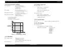
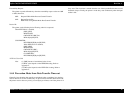
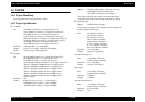
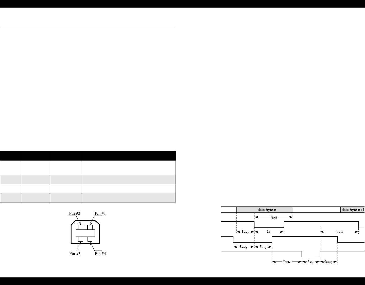
Data transmission timing :
Pin No. Signal name In/Out Function description
1VCC -
Cable power. Maximum power consumption is
100mA
2 Data bi-directional Data
3 +Data bi-directiona data, pull up to +3.3V via 1.5K ohm resistor
4 Ground - Cable ground
DATA
-STROBE
BUSY
-ACKNLG