


Stylus C40UX/C40SX/C20UX/C20SX Revision A
Troubleshooting Overview 45
3.1 Overview
This chapter describes how to identify troubles in two levels: unit level repair and
component level repair. Refer to the flowchart in this chapter to identify the defective
unit and perform component level repair if necessary. This chapter also explains motor
coil resistance, sensor specification and error indication.
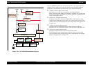
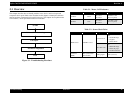
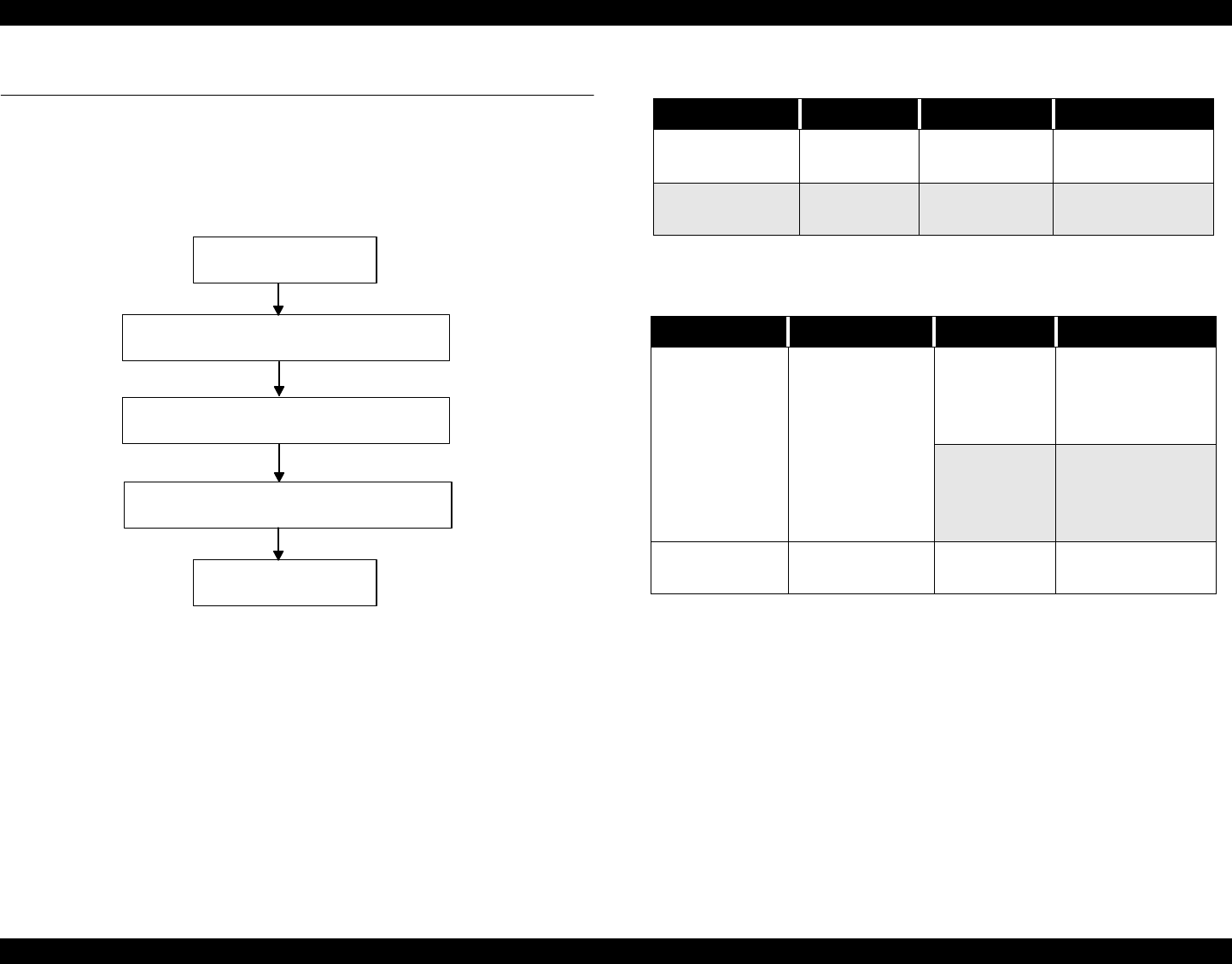
Figure 3-1. Troubleshooting Flowchart
START
Unit level Troubleshooting
Unit repair
Assemble & Adjustment
END
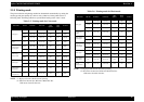
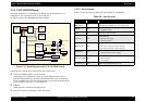
Table 3-1. Motor, Coil Resistance
Motor Location Check Point Resistance
CR Motor CN12
Pin 1 and 3
Pin 2 and 4
9.6 Ohms
±
10%
(at 25
°
C/ phase)
PF Motor CN7
Pin 1 and 3
Pin 2 and 4
7.35 Ohms
±
10%
(at 25
°
C/ phase)
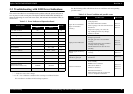
Table 3-2. Sensor Check Point
Sensor Name Check Point Signal Level Switch Mode
HP/PE Sensor CN4/Pin 1 and 2
Less than 0.7V
Off
• Out of HP range
• No paper
•Detect the I/C
More than 2.4V
On
• Within HP range
• Detect the paper
• Not detects the I/C
Thermistor
(THM)
TH1 (on the Head
driver board)
Analog signal 10 K (at 24
°
C)