


Stylus C40UX/C40SX/C20UX/C20SX Revision A
Operating Principles Electrical Circuit Operating Principles 43
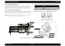
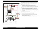
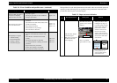
2.2.2 C413 MAIN/B Board
The printer mechanism is controlled by C413MAIN. On this MAIN board, 3.3V
regulator IC is not mounted and all IC is driven with 5.0 V.
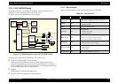
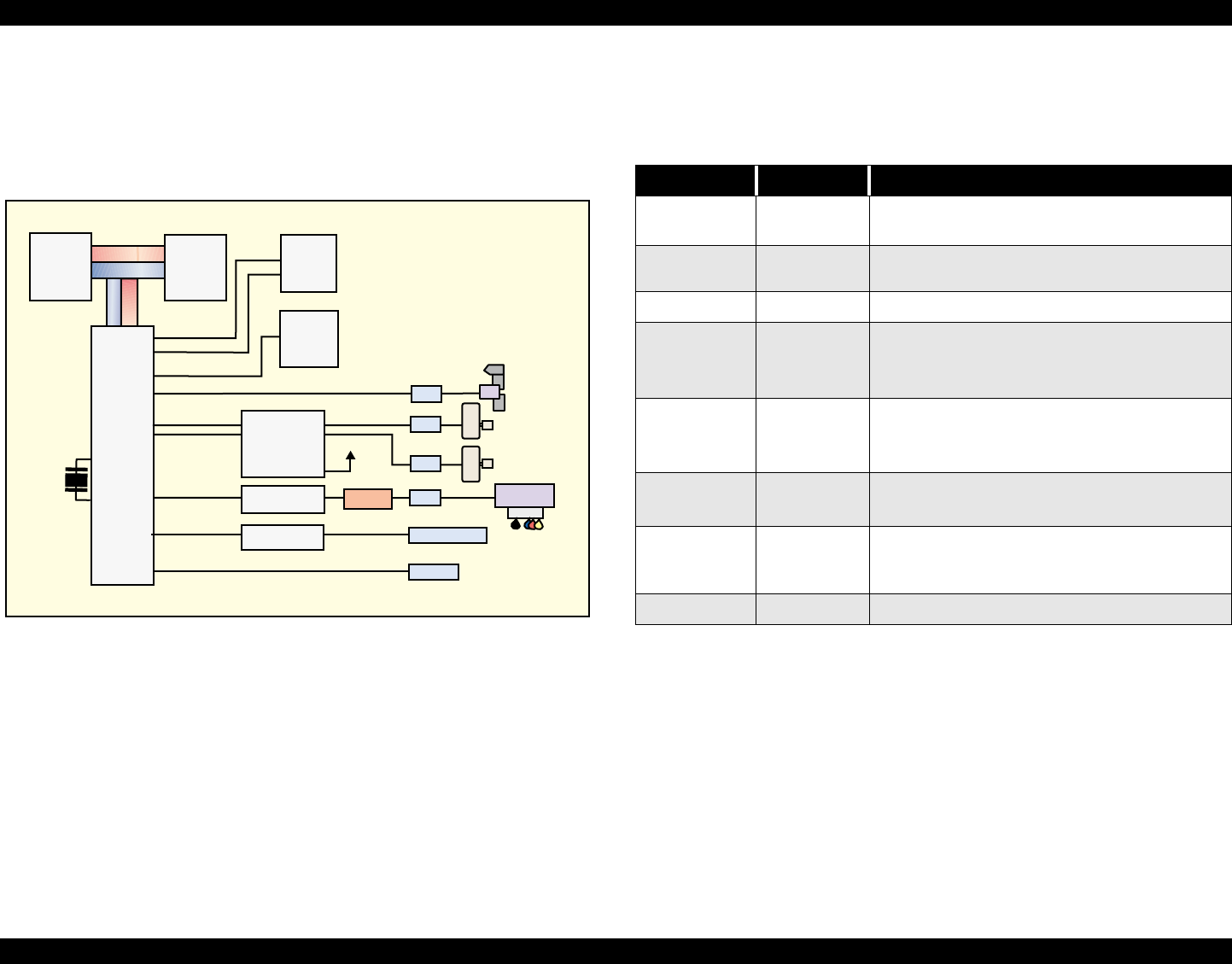
See Figure for the C413 MAIN/B board block diagram.
Figure 2-21. Block Diagram for the (C413 MAIN/B) Board
Following shows you the major characteristic of this main board.
Timer IC & Lithium battery are not mounted
Unlike the previous products, the Timer IC and the Lithium battery are not
mounted on the Main board. So, this product perform the Power-on cleaning or
Timer cleaning based on the time command which is sent from the printer driver.
As for the detail, refer to the 2.1.7 Ink Sequence.
D-RAM
1Mbit D-RAM is mounted on the Main board.
One CPU controls the all function on the main board.
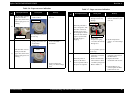
2.2.2.1 Main elements
Table 2-8 shows the function of the each main elements on C413MAIN.
PROM 4M
(IC6)
Address
Data
D-RAM 1M
(IC5)
Reset IC
(IC2)
EEPROM
(IC3)
CR1
Motor Driver
(IC10)
+5V
Common Driver
(IC9)
Q2 & Q3
CN7
CN12
CN4
CN9
CN7 Parallel I/F
Common Driver
(IC7)
CN3 USB
Head
CR Motor
PF Motor
HP/PE/IC Sensor
(C413MAIN-B)
(C413MAIN)
E01A24CA
CPU (IC1)
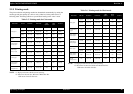
Table 2-8. Main Elements
IC Location Function
ASIC
E01A24NA
IC1
16bit CPU mounted on the MAIN board is driven by
clock frequency 24MHz and controls the printer.
PROM IC6
• Capacity 4MB, Bus= 16 bit
• Program for CPU
RAM IC5 Bus= 16 bit, 1Mbit DRAM
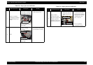
AT93C46 IC3
1kbit EEPROM
• Default value setting
• Parameter backup
BH6150F-E2 IC2
Reset IC
• For +5V; reset when +4.2V is detected
• For +36V, reset when +29.2 is detected
E09A39RA IC9
Head drive control HIC
• Generates head common voltage.
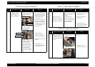
XC901503FNR2 IC10
• CR motor driver
•PF motor driver
• +5V regulator
74LVX161284 IC7 IEEE1284 parallel I/F transceiver IC.