


Stylus C40UX/C40SX/C20UX/C20SX Revision A
Operating Principles Overview 36
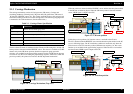
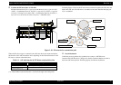
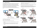
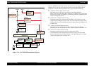
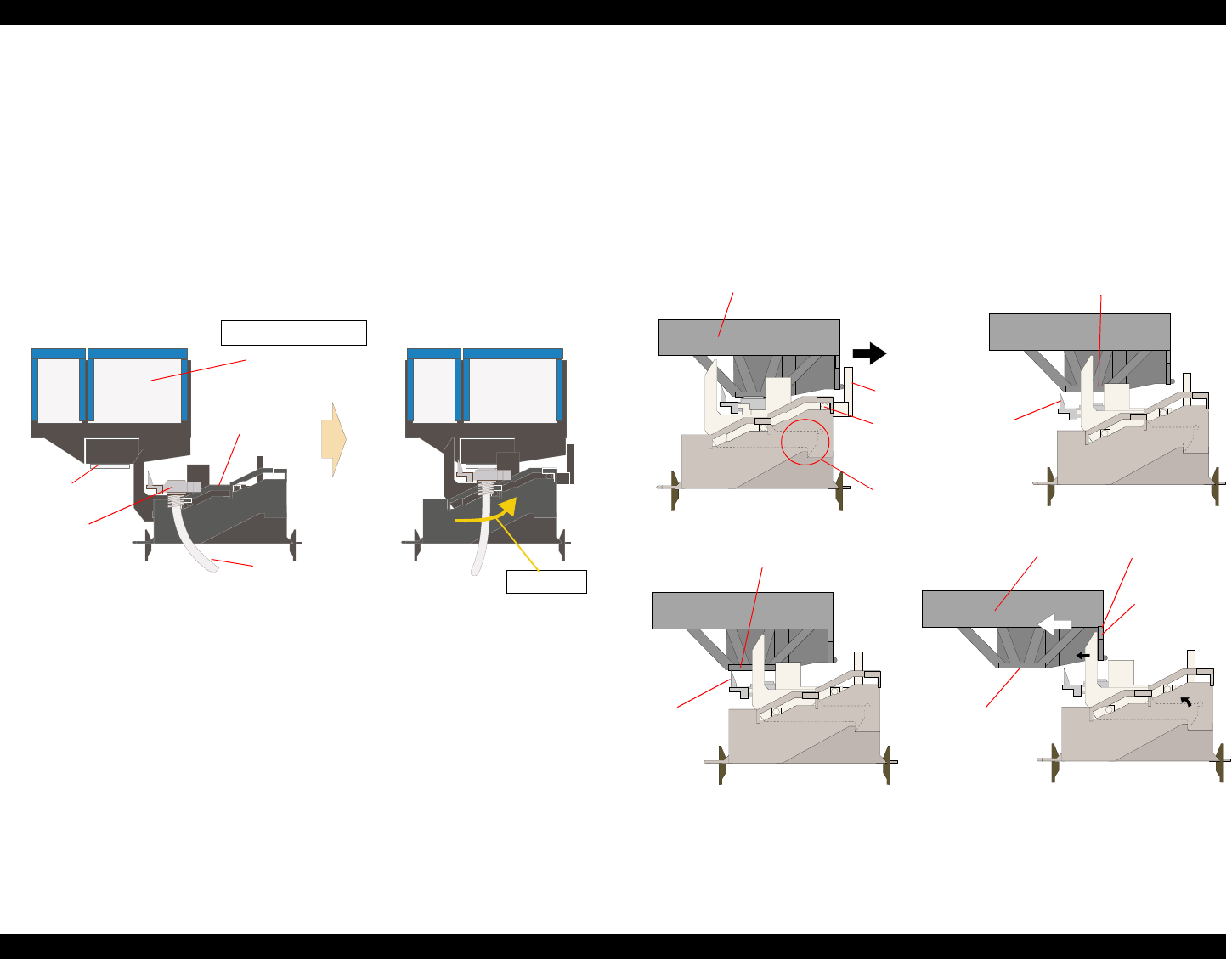
2.1.6.2 Capping Mechanism
The capping mechanism covers the printheads with the cap holder to prevent the nozzle
from increasing viscosity when the printer is in stand-by mode or when the printer is
off. This product has valveless cap system. Air valve function used for the previous
models pumps and ejects ink only inside the cap by absorbing ink with the valve open.
By opening the Air valve, the negative pressure is decreased and only the ink inside the
cap is ejected. (the ink is not absorbed from Ink cartridge or head cavity.)
But, valveless cap system, this operation is done out side of the capping area.
The CR moves to left side of the Cap assembly and the pump absorbs the ink inside the
cap.
Figure 2-16. Cap Mechanism
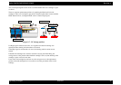
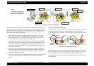
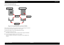
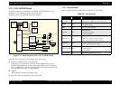
Also, unlike previous models, the cap unit is newly designed for this model as follows.
2.1.6.2.1 Wiper with the cap unit
Wiping control is carried out by the procedure shown below.
1. The carriage is moved to the wiper set position. (Refer to Figure 2-17. Wiper Set
Position)
2. When the carriage moves to the wiper set position, the hook on the lever lock
slider engages, locking the lever lock slider. (Refer to Figure 2-17. Wiper Set
Position)
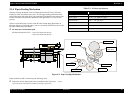
3. If the carriage moves to the left side, spring forces tends to force the cap back to its
original position, but it stops at the wiping position due to the lever lock slider.
(Refer to Figure 2-17. Wiping Position)
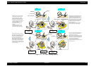
4. When the carriage moves to the left side, the head surface and wiper makes contact
and wiping is performed. (Refer to Figure 2-17. Wiping Position)
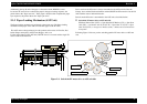
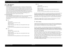
5. Even when wiping is completed, the carriage moves further to the left side and
when the hook on the carriage’s right side hits the lever lock slider lever, the lever
lock slider’s hook is released. (Refer to Figure 2-17. Wiper Set Release)
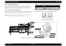
CR unit
Cap
Viewed from front side
Printhead
Slider cap
Waste Ink tube
Slide up
The carriage
pushes the lever.
Right side from
capping position
The hook is
released.
Figure 2-17. Wiping
Figure 2-17. Wiper Set Position
Figure 2-17. Wiping Position
Figure 2-17. Wiper Release
Hook
Carriage unit
Print head
Wiper
Carriage unit
Wiper
Print head
Hook
Print head