


CHAPTER 1: INTRODUCTION INTRODUCTION
MULTILINK ML1200 MANAGED FIELD SWITCH – INSTRUCTION MANUAL 1–5
POWER CONSUMPTION
35 watts worst case (for a fully loaded fiber model)
12 watts typical (for a small 4 port copper-only model)
DUAL DC POWER INPUT (OPTIONAL)
A Dual-Source option is available for the 12VDC, 24VDC, – 48VDC, and 125VDC models (not the
250VDC model). This provides for continuity of operation when either of the DC input sources is
interrupted. See Appendices B and C.
The Dual-Source Terminal Block is marked:..............................“ –A, -B, +A, +B ”
ML1200 MOUNTING
Vertical mounting normal. Suitable for wall or DIN-Rail mounting (ML1200)
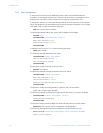
TYPE TESTS
TEST REFERENCE STANDARD TEST LEVEL
Electrostatic Discharge EN61000-4-2 Level 4
RF immunity EN61000-4-3 Level 3
Fast Transient Disturbance EN61000-4-4 Level 3 & 4
Surge Immunity EN61000-4-5 Level 4
Conducted RF Immunity EN61000-4-6 Level 3
Power magnetic Immunity IEC61000-4-8 Level 2
Voltage Dip & interruption IEC61000-4-11
0,40,70% dips,250/300cycle
interrupts
Environmental (Cold) DNV 2.4 -25 C
Environmental (Dry heat) DNV 2.4 70C
Relative Humidity Cyclic DNV 2.4 2 day
Radiated & Conducted
Emissions
CISPR22/ IEC60255-25 Class A
Radiated & Conducted
Emissions
FCC Part 15 Subpart B Class A
Safety EN60950-1 stanadard
Harmonics EN61000-3-2
Flicker EN61000-3-3
Ingress Protection IEC60529 IP20A
Sinusoidal Vibration DNV 2.4 1 to 4 G