


3–6 MULTILINK ML1200 MANAGED FIELD SWITCH – INSTRUCTION MANUAL
INSTALLATION CHAPTER 3: INSTALLATION
3.3 Mechanical Installation
3.3.1 DIN-Rail Mounting the Multilink ML1200
The Multilink ML1200 is designed for use in a “factory floor” industrial environment. It is
available with optional DIN-Rail brackets to mount it securely in a metal factory floor
enclosure, maintained vertically for proper convection cooling of the unit. The Multilink
ML1200 requires one DIN-Rail mounting clip or latch for secure mounting. These may be
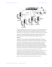
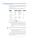
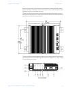
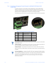
ordered as Model # DIN-RAIL-ML1200. See a ML1200 viewed from the side, at the left, with
model DIN-RAIL-ML1200 in place on the unit.
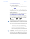
The Din Rail Latching clips are mounted on the upper side corners of the ML1200 unit. Two
threaded holes are provided on the sides of ML1200 for DIN-Rail mounting purposes. See
side view at the left. The required two screws are included with the DIN-Rail brackets, and
are no.10-32 X 3/8 PHIL. PAN w/star washer. The two heavy-duty Din-Rail latches are
designed as if that they can be manually accessed from the top when the ML1200 is
installed on a DIN Rail.
To install the ML1200 with the DIN-Rail brackets and latches attached to it, hold the
ML1200 in the side vertical position with the bottom out, and with the top moved in toward
the DIN-Rail. Position the latches over the top of the DIN-Rail. Then, snap the latches into
holding position by moving the bottom of the ML1200 inwards to a vertical position. The
DIN-Rail latches and brackets are heavy duty, and will hold the ML1200 securely in
position, even with cabling attached to the unit.
To release the ML1200 from the DIN-Rail mounting, press the top of the two DIN-Rail
latches down simultaneously to release the ML1200 so that it can be dismounted by
pulling the bottom out. Once the bottom of the ML1200 is rotated out, the DIN-Rail latch is
not engaged and the ML1200 can be moved up and out, free of the DIN-Rail mounting.
If the Multilink ML1200 is to be mounted on a DIN-Rail track, for proper convection cooling
of the unit there must be air space in the rear, as the ML1200 unit is held out from the rear
of the panel by the mounting brackets. The ML1200 design uses the case for cooling
(patent pending), and needs to be mounted vertically with air flow space around it in the
front, rear, and sides.
The DIN-Rail mounting brackets and latches are optional and need to be ordered as
separate items, e.g Model # DIN-RAIL-ML1200
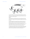
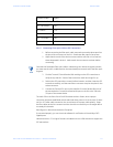
3.3.1.1 Mounting Dimensions for ML1200 with metal brackets
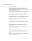
Each Multilink ML1200 is supplied with metal mounting brackets and screws to mount the
unit securely on a panel or wall. It is recommended to mount the ML1200 vertically, as
shown below, for proper cooling and long-life reliability. It is also advisable to mount the
unit with space for air movement around the top and the sides, typically a minimum of 1
inch.
Note that the metal brackets supplied hold the back of the ML1200 unit out from the panel
or wall behind it, creating a rear space of about ¼ inch or 1cm. This allows air circulation
and cooling of the rear part of the case.