


10–2 MULTILINK ML1200 MANAGED FIELD SWITCH – INSTRUCTION MANUAL
VLAN CHAPTER 10: VLAN
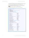
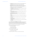
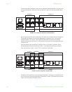
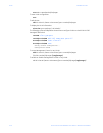
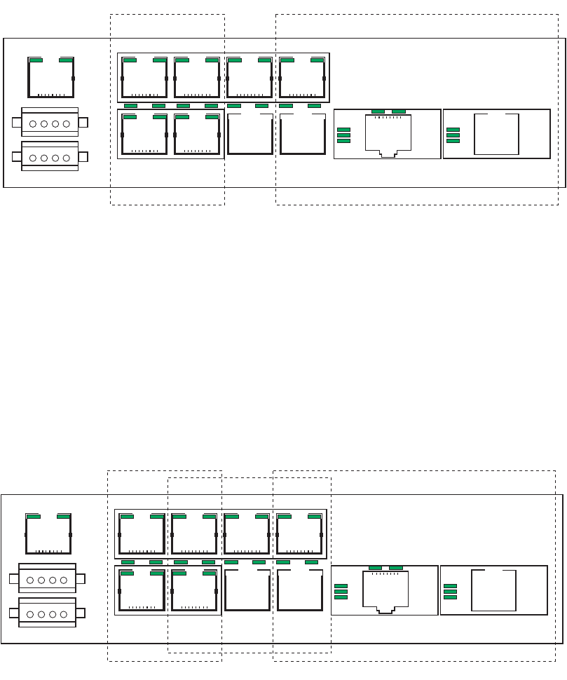
The following figure illustrates a VLAN as two separate broadcast domains. The top part of
the figure shows two “traditional” Ethernet segments. Up to 32 VLANs can be defined per
switch.
FIGURE 10–1: VLAN as two separate broadcast domains
A group of network users (ports) assigned to a VLAN form a broadcast domain. Packets are
forwarded only between ports that are designated for the same VLAN. Cross-domain
broadcast traffic in the switch is eliminated and bandwidth is saved by not allowing
packets to flood out on all ports. For many reasons a port may be configured to belong to
multiple VLANs.
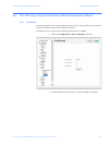
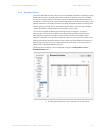
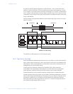
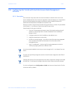
As shown below, ports can belong to multiple VLANs. In this figure, a simplistic view is
presented where some ports belong to VLANs 1, 2 and other ports belong to VLANs 2,3.
Ports can belong to VLANs 1, 2 and 3. This is not shown in the figure.
FIGURE 10–2: Ports assigned to multiple VLANs
By default, on the MultiLink ML1200 Managed Field Switch, VLAN support is enabled and all
ports on the switch belong to the default VLAN (DEFAULT-VLAN). This places all ports on the
switch into one physical broadcast domain.
CONSOLE
POWER
VLAN 1 VLAN 2
SEGMENT 1 SEGMENT 2
CONSOLE
POWER
VLAN 1
VLAN 2
SEGMENT 1
SEGMENT 2
SEGMENT 3
VLAN 3