


CHAPTER 3: INSTALLATION INSTALLATION
MULTILINK ML1200 MANAGED FIELD SWITCH – INSTRUCTION MANUAL 3–3
3.2.0.2 Connecting Fiber Optic SC-type, "Snap-In"
The following procedure applies to installations using a PM with SC-type fiber connectors,
i.e., using C9 Module, CA Module single-mode:
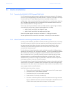
When connecting fiber media to SC connectors, simply snap on the two square
male connectors into the SC female jacks of the PM, until it clicks and secures.
3.2.0.3 Connecting Single-Mode
Fiber Optic
When using single-mode fiber cable, be sure to use single-mode fiber port connectors.
Single-mode fiber cable has a smaller diameter than multi-mode fiber cable (9/125
microns for single-mode, 50/125 or 62.5/125 microns for multi-mode where xx/xx are the
diameters of the core and the core plus the cladding respectively). Single-mode fiber
allows full bandwidth at longer distances, and may be used to connect 10 Mb nodes up to
10 Km apart, or 18Km with the ML1200.
The same procedures as for multi-mode fiber, applies to single-mode fiber connectors.
3.2.0.4 Connecting Twisted Pair (CAT3, CAT5, Unshielded or Shielded)
The RJ-45 ports of the Multilink ML1200 can be connected to the following two media
types: 100BASE-TX and 10BASE-T. CAT 5 cables should be used when making 100BASE-TX
connections. When the ports are used as 10BASE-T ports, CAT 3 may be used. In either
case, the maximum distance for unshielded twisted pair cabling is 100 meters (328 ft).
Note
It is recommended that high quality CAT. 5 cable be used whenever possible in order to
provide flexibility in a mixed-speed network, since 10/100 copper switched ports are auto-
sensing for either 10 and 100Mb/s.
The following procedure describes how to connect a 10BASE-T or 100BASE-TX twisted pair
segment to the RJ-45 port. The procedure is the same for both unshielded and shielded
twisted pair cables.
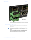
1. Using standard twisted pair media, insert either end of the cable with an RJ-
45 plug into the RJ-45 connector of the port. Note that, even though the
connector is shielded, either unshielded or shielded cables and wiring may be
used.
2. Connect the other end of the cable to the corresponding device
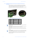
3. Use the LINK LED to ensure proper connectivity by noting that the LED will be
illuminated when the unit is powered and proper connection is established
Note
For Power Substations: In support of the IEEE 1613 Class 2 standard, GE Multilin advises
that, for substation applications, the RJ-45 ports are intended for connectivity to other
communication equipment such as routers or telecommunication multiplexers installed in
close proximity (i.e., less than 2 meters or 6.5ft) to the ML1200. It is not recommended to
use these ports in substation applications to interface to field devices across distances
which could produce kigh (greater than 2500V ) levels of ground potential rise (GPR) during
line-to-ground fault conditions. The ML1200 passes the 1613specifications for zero packet
loss with fiber ports & with RJ-45 ports used as indicated here.
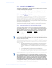
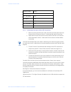
Media IEEE Standard Connector
Twisted Pair (CAT 3, 4, 5) 10BASE-T RJ-45
Twisted Pair (CAT 5) 100BASE-TX RJ-45