


4–6 MULTILINK ML1200 MANAGED FIELD SWITCH – INSTRUCTION MANUAL
OPERATION CHAPTER 4: OPERATION
4.2 Multilink ML1200 Managed Field Switch Port Modules
This chapter describes each Port Module (PM), including appearance, functionality, and
status displays.
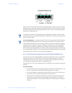
4.2.1 Inspecting the Package and Product
This section applies only to Port Modules shipped as separate items, i.e., ML1200 PMs that
are not factory installed.
Examine the shipping container for obvious damage prior to installing a ML1200 PM; notify
the carrier of any damage you believe occurred during shipment. Inspect the contents of
this package for any signs of damage and ensure that the items listed below are included.
The package should contain:
• 1 or more ML1200 Port Moduless
• Installation instructions with illustrations
Observing proper ESD grounding procedures, remove the ML1200 PM(s) from the shipping
container. Be sure to keep the shipping container should you need to ship any of the PMs
separately at a later date. In the event there are items missing or damaged, contact your
supplier. If you need to return the unit, use the original shipping container if possible. Refer
to Chapter 5 for specific return procedures.
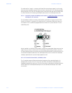
4.2.2 ML1200 Modules
An important feature of the Multilink ML1200 is the use of Port Modules for flexible mixed-
media connectivity to RJ-45 copper and various fiber media. The first four ports (1,2,3 & 4)
of the Multilink ML1200 Switches are fixed RJ-45 copper ports with dual-speed 10/
100Mbps auto-negotiating capability. Additionally the switch can accept up to three Port
Modules to provide the user with up to 12 additional ports (16 total) providing a wide
selection of Ethernet copper and fiber media connections with 10, 100 and 1000Mbps
capability and up to 70km.
Note
The ML1200 Port modules are not identical to the port modules used in other Multilink
products such as the ML2400 and ML1600. For information about other Multilink
products, please see the applicable manual. For a list of ML1200 Port Modules, refer to
Section 2.1.
Each ML1200 Port Module (PM) is individually described in the sections that follow.
For the fiber modules in slot D, the operational description is the same as the
corresponding fiber modules configured in slots B and C described below.
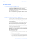
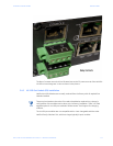
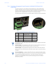
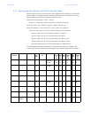
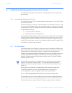
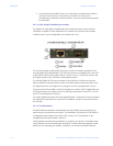
4.2.2.1 C8 Module, 2@100Mb multi-mode FX-ST “twist lock” Combo Module
The C8 Module is two port ST fiber module at 100MB. The module is equipped with dual-
mode ST-type connectors and dual speed copper ports. The ST-connector functions as a
fiber optic transceiver to support 100BASE-FX network segments. When installed in a