


CHAPTER 3: INSTALLATION INSTALLATION
MULTILINK ML1200 MANAGED FIELD SWITCH – INSTRUCTION MANUAL 3–5
3.2.0.7 Connecting Fiber Optic Cable to SFP Transceivers
1. Before connecting the fiber optic cable, remove the protective dust caps from
the tips of the connectors on the PM. Save these dust caps for future use.
2. Wipe clean the ends of the dual connectors with a soft cloth or lint-free lens
tissue dampened in alcohol. Make certain the connectors are clean before
connecting.
Note
One strand of the duplex fiber optic cable is coded using color bands at regular intervals;
you must use the color-coded strand on the associated ports at each end of the fiber optic
segment.
3. Find the Transmit (TX) and Receive (RX) markings on the SFP transceiver to
verify the top side of it. Some of the transceiver marks arrow sign for up.
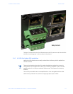
4. Position the SFP transceiver correctly before insertion, and then insert the SFP
transceiver carefully, until the transceiver connector snap into the place in the
socket connector.
5. Connect the Transmit (TX) port on the Multilink PM to the Receive (RX) port of
the remote device. Connect the Receive (RX) port on the PM to the Transmit
(TX) port of the remote device.
The LINK LED on the front of the PM will illuminate and turn Green, when a proper
connection has been established at both ends (and when power is ON in the unit). If LINK is
not lit or OFF after cable connection, the normal cause is improper cable polarity. Swap
the fiber cables at the PM connector and also check the connectivity on the target device
to remedy this situation.
Reconfigure or reboot both the device if required.
If connected properly, you can check via software for verification of the validity of SFP
Gigabit ports.
Make sure Version 3.3 or higher firmware is loaded on the ML1200 switches to support the
SFP transceivers.
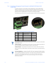
Module Model# Gigabit
Gb Modules, fixed ports--SFP
H1 - H6 Module 2 SFP
H7 Module 2 CU
H8 - HD Module 1SFP, 1CU
HE - HJ Module 1 SFP
HK Module 1 CU