


C–2 MULTILINK ML1200 MANAGED FIELD SWITCH – INSTRUCTION MANUAL
INTERNAL DC DUAL-SOURCE POWER INPUT OPTION CHAPTER C: INTERNAL DC DUAL-SOURCE POWER INPUT OPTION
C.1 Specifications for Multilink ML1200 Field Switch
Power Supply (Internal, -48VDC Dual-Source)
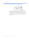
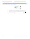
DC Power Connector: First Source: “A+”, “A-“, 2nd Source “B-“, “B+”
GND: ground wire connection to the hub chassis screw
Input: Two separate sources, each at 36 - 60 VDC
Power Supply (Internal, 12VDC Dual-Source, model # Dual-Src-12V)
DC Power Connector: First Source: “A+”, “A-“, 2nd Source “B-“, “B+”
GND: ground wire connection to the hub chassis screw
Input: Two separate sources, each at 8-18 VDC
Power Supply (Internal, 24VDC Dual-Source, model # Dual-Src-24V)
DC Power Connector: First Source: “A+”, “A-“, 2nd Source “B-“, “B+”
GND: ground wire connection to the hub chassis screw
Input: Two separate sources, each at 18 - 36 VDC
Power Supply (Internal, 125VDC Dual-Source, model # Dual-Src-125V)
DC Power Connector: First Source: “A+”, “A-“, 2nd Source “B-“, “B+”
GND: ground wire connection to the hub chassis screw
Input: Two separate sources, each at 88 - 150 VDC
Power Supply (Internal, 250VDC Dual-Source, model # Dual-Src-250V)
DC Power Connector: First Source: “A+”, “A-“, 2nd Source “B-“, “B+”
GND: ground wire connection to the hub chassis screw
Input: Two separate sources, each at 160 - 300 VDC
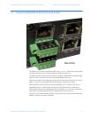
With the exception of the dual DC input power connections and the power supply, all
specifications and configuration options for the Multilink ML1200 -48VDC, 12VDC, 24VDC,
125VDC and 250VDC models with this Dual-Source option are identical to those listed in
the Multilink ML1200 Field Switches Installation and User Guide, including Appendix x
“Internal DC Power Supply Option”