


CHAPTER 2: PRODUCT DESCRIPTION PRODUCT DESCRIPTION
MULTILINK ML1200 MANAGED FIELD SWITCH – INSTRUCTION MANUAL 2–5
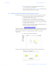
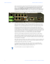
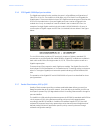
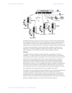
The LEDs on C2 PoE modules are slightly different compared to regular (non-PoE) RJ-45
modules as shown in the figure below. When the PoE port is in use, the PoE LED is ON when
connected properly to an 803.af compliant PD device on that port. When non-PoE devices
are connected, the PoE LED is OFF. The operation of Ethernet data traffic is not affected by
PoE.
LINK and ACTIVITY LEDS are combined on the PoE modules into one LED that is marked as
LINK/ACT, as shown in the diagram.
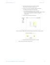
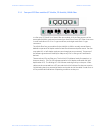
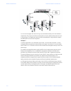
2.1.4 Two-Port Fiber Modules, 2@ 100Mb fiber
The two-port modules are available as two 100Mb fiber ports. ST or SC connector styles
are available utilizing multi-mode or single-mode fiber optics. These fiber modules may be
factory configured with a choice of them in slots B, C, and D only.
The fiber port’s LEDs indicate status the same as the SFF fiber modules. Color-coding on
the panel of the module shows which LEDs belong to which port.
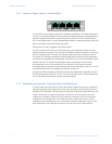
2.1.5 Two -Port 10 Mb mm Fiber ST Modules
The 2-port @10Mb ST fiber modules behave the same as the 2@100Mb ST fiber modules
except for the 10Mb speed.
The default setup on the 10Mb fiber module is half-duplex, which allows the Multilink
ML1200 Switch to connect to any 10Mb hub or media converter or almost any other device
with a 10Mb fiber Ethernet port. The default setting of the 100Mb fiber module is full
duplex. User mode-control per port through the “port settings” is the same as the other
ML1200 modules.
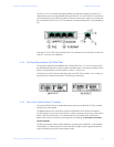
The fiber ports support fiber cabling distances according to the 10BASE-FL and 100BASE-
FX standards, i.e., 2km distance for multi-mode fiber. (Single-mode for greater distances
may be available as a special order, request quote).