


System Administrator Screens
312353B 35
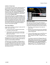
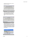
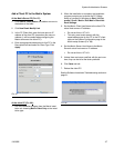
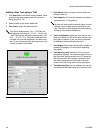
Transceiver Setup
Click Add Transceiver Button, then click Modify.
1. Enter the area of the shop where the transceiver is
located (i.e., Main Shop, Fast Lube Shop, Engine
Department) in the Transceiver Name field.
2. The Network ID is a letter designation for the Trans-
ceiver network identification. The default is (A).
There are eight network ID’s available designated
with the letters A through H. Type in the selected
Network ID.
The Network ID letter for a given Transceiver
must match that Transceiver’s dipswitch set-
tings.
3. Transceiver ID is a letter designation for the Trans-
ceiver Identification. The default is (A). There are
eight Transceiver ID’s available designated with the
letters A through H.
The Transceiver ID letter for a given Transceiver
must match that Transceivers equivalent dip-
switch settings.
4. Serial Port is a pull down menu of all available com-
munication ports on the Matrix PC. COM 1 is the
default setting. If COM 1 is not available, select an
open port from the pull down list.
Some computers may not have any serial ports.
In this case a USB converter will be required to
obtain serial ports. Graco recommends Edge-
port models from B & B Electronics.
If you attempt to add a Transceiver and the PC
has no COM ports available, an error message
appears. Contact your IT professional or add
serial ports using the USB convertors recom-
mended by Graco. See page 4 for additional
information.
Firmware Revision is the Transceiver firmware
revision level.
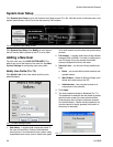
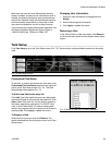
Transceiver Power-up
Graco recommends that when you plug in the power
cord to the transceiver, do it with the PC serial cable
already plugged in.
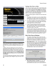
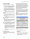
Confirm PC/Transceiver Communication
Each time a transceiver is powered up, it reads its dip
switch settings for Network ID and Transceiver ID and
sends this information to the PC. It also sends the trans-
ceiver’s firmware revision level. These settings are dis-
played as “Last Power-up Settings” and “Firmware
Revision” on this screen. If these fields are “N/A”, it
means that the transceiver has never (successfully)
communicated with the PC.
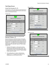
One way to confirm that the serial connection between
PC and transceiver is functioning properly is to change
the transceiver dip switch settings and verify that the PC
software reflects the new settings. Refer to the trans-
ceiver manual on how to set transceiver dip switches.
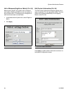
Example:
A Matrix system has a single transceiver, the desired
settings on the transceiver setup screen (F
IG. 66) are
Network ID = A, Transceiver ID = A, and Serial Port =
COM1 (factory defaults).
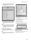
1. If it’s open, close the transceiver setup screen (F
IG.
66).
2. Power off the transceiver.
3. Set the transceiver dipswitch settings to:
Network ID = H
Transceiver ID = H
Refer to transceiver manual 309498 for instructions.
4. With one end of the serial cable already plugged
into the PC and the other end in the transceiver,
power up the transceiver.
FIG. 66