


MultiProcessor Specification
4-4 Version 1.4
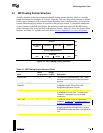
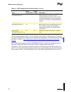
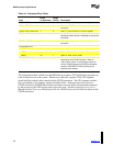
Table 4-1. MP Floating Pointer Structure Fields (continued)
Field
Offset
(in bytes:bits)
Length
(in bits) Description
MP FEATURE
INFORMATION BYTE 1
11 8
Bits 0-7:
MP System Configuration Type.
When these bits are all zeros, the MP
configuration table is present. When nonzero,
the value indicates which default configuration
(as defined in Chapter 5) is implemented by the
system.
MP FEATURE
INFORMATION BYTE 2
12:0
12:7
7
1
Bits 0-6:
Reserved for future MP definitions.
Bit 7:
IMCRP. When the IMCR presence bit is
set, the IMCR is present and PIC Mode is
implemented; otherwise, Virtual Wire Mode is
implemented.
MP FEATURE
INFORMATION BYTES 3-5
13 24 Reserved for future MP definitions. Must be
zero.
The MP feature information byte 1 specifies the MP system default configuration type. If nonzero,
the system configuration conforms to one of the default configurations. The default configurations,
specified in Chapter 5, may only be used to describe systems that always have two processors
installed.
Bit 7 of MP feature information byte 2, the IMCR present bit, is used by the operating system to
determine whether PIC Mode or Virtual Wire Mode is implemented by the system.
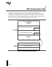
The physical address pointer field contains the address of the beginning of the MP configuration
table. If it is nonzero, the MP configuration table can be accessed at the physical address provided
in the pointer structure. This field must be all zeros if the MP configuration table does not exist.